|

|
Forum Index : Microcontroller and PC projects : MIXTEL90 can we chat about one of your Children?
| Author | Message | ||||
| Rickard5 Guru Joined: 31/03/2022 Location: United StatesPosts: 463 |
Mixtel, Way back when before I took some time off You had designed some Arduino form factor Picomites. I built one today, and I can't. find any of the info or notes is can you tell me What the option sdcard string is ? and can you tell me the value of C3 and what it is ? and the rest of the BOM I would like to Build as complete one, and explore the designers full intentions Thank you Mixtel I may be Vulgar, but , while I'm poor, I'm Industrious, Honest, and trustworthy! I Know my Place |
||||
| phil99 Guru Joined: 11/02/2018 Location: AustraliaPosts: 2135 |
So from your top pic:- OPTION SDCARD gp2, gp4, gp3, gp22 However I wonder if that is a misprint, that sequence is unusual. I would have expected:- OPTION SDCARD gp22, gp2, gp3, gp4 Edit. Not a misprint. Found the circuit in the Construction pack.zip here Edited 2024-07-06 11:32 by phil99 |
||||
| Rickard5 Guru Joined: 31/03/2022 Location: United StatesPosts: 463 |
Hey Thanks Phil, I'm gonna give it a try right after I get this board out of the ultrasonic cleaner! which is a nice Segway to my next topic what do you put in Ultrasonic to wash boards? I may be Vulgar, but , while I'm poor, I'm Industrious, Honest, and trustworthy! I Know my Place |
||||
| phil99 Guru Joined: 11/02/2018 Location: AustraliaPosts: 2135 |
See Edit in my last post. Re ultrasonic washing, I have used water with a very small amount of dishwashing detergent. Don't know if that is the proper way but it seemed to work ok. |
||||
| Mixtel90 Guru Joined: 05/10/2019 Location: United KingdomPosts: 6783 |
I don't usually make any special effort to choose pins for the SD card unless I am already specifying system SPI. There's no point as it doesn't need a hardware SPI module in the RP2040. I just make the connections where they work out easiest. :) It'll be interesting to see how you get on with that, Rick. :) Mick Zilog Inside! nascom.info for Nascom & Gemini Preliminary MMBasic docs & my PCB designs |
||||
| Rickard5 Guru Joined: 31/03/2022 Location: United StatesPosts: 463 |
@ Mick Well I'm doing something Wrong somewhere Every Picomite board I've built I can't get the SD Card to work unless I Hotwire the SD Card socket strait to pins. I have no idea what I'm doing wrong, I've been checking solder joints under microscope and I've even washed boards for 12-14 hopped in ultrasonic to get of flux. I have 4 more of these Arduino boards I'm gonna try. is there any passives I'm missing or do I only need the socket and the Pico? THANKS Man Rickard Edited 2024-07-07 16:07 by Rickard5 I may be Vulgar, but , while I'm poor, I'm Industrious, Honest, and trustworthy! I Know my Place |
||||
| phil99 Guru Joined: 11/02/2018 Location: AustraliaPosts: 2135 |
Arduino's are 5V and SD cards are 3.3V and are destroyed by 5V. So Arduino SD modules usually have a 3.3V regulator and signal level shifters on them. The Pico is 3.3V so the regulator output may be too low. Measure it, 3V is about the minimum for most cards. Bypassing the regulator may help but there may still be some signal lost through the level shifters. Some cards can tolerate that but not all. Direct connection is all that is needed for most cards. Some need extra supply filtering, 10µF or so. Edit. If you power the module from 5V the SPI output will also be 5V which the Pico may not like. 1kΩ series resistors in all the signal lines might save the Pico, maybe. Edited 2024-07-07 17:14 by phil99 |
||||
| Mixtel90 Guru Joined: 05/10/2019 Location: United KingdomPosts: 6783 |
Rick, please list your OPTION list and a list of connections, e.g. OPTION SDCARD GP1, GP2, GP3, GP4 PICO - SDCARD GP1 - MISO GP2 - SCLK GP3 - MOSI GP4 - CS 3V3 - VCC GND - GND Note, the above won't work, it's merely an example. The signal pins might be DI and DO rather than MISO and MOSI on the SDcard. If the SD card works on the breadboard but not on the PCB then you have a PCB track problem. You will have to test every track to the SD card socket with a meter - even a microscope is no use as breaks can be extremely small and the gap filled with solder resist. You will also have to test for short circuits between adjacent pins in that area of the Pico. If you haven't got a meter (you haven't confirmed or denied that yet) then there is another way. Without setting OPTION SDCARD (and without one plugged in) set all the pins donnected to the SD card to digital inputs. Then , for each in turn, watch the pin in MMBasic while you connect the SD card end to 3V3 and GND. You should see each one change. Your original problem was with the Type 1 VGA PCB, wasn't it? Are you now having problems with my Arduino-style design too? Are you sure you are using the correct MMBasic commands to use the SD card in both cases? The ArdoMite pcb looks right, the Type 1 VGA pcb is known to work properly. They use different SD card sockets, so it's not something that's common to those. It's possible, of course, that every SD card that you've tried is faulty, but it's unlikely. . Edited 2024-07-07 18:34 by Mixtel90 Mick Zilog Inside! nascom.info for Nascom & Gemini Preliminary MMBasic docs & my PCB designs |
||||
| lizby Guru Joined: 17/05/2016 Location: United StatesPosts: 3150 |
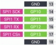
Rick--I've used a module which looks like yours many times. For mine, the pins are 3v3, cs, mosi, clk, miso, 0V. You appear to be using pins 14, 15, 16, 17 (GP10-13). It looks to me like you are using 16 for CS, 14 for MOSI, 15 for CLK, and 17 for MISO. Based on the standard pinout, I would say that 14 should be CLK, 15 MOSI, 16 MISO, and 17 CS, or OPTION SDCARD 14,16,15,17 (GP10,GP12,GP11,GP13), or OPTION SYSTEM SPI 14,15,16 ((GP10,GP11,GP12) and OPTION SDCARD 17 (GP13).  Untested, and I may have confused myself--but that's what I would try--rewiring and resetting the OPTION(s). (But I have to say, I'm rusty here.) PicoMite, Armmite F4, SensorKits, MMBasic Hardware, Games, etc. on fruitoftheshed |
||||
| Rickard5 Guru Joined: 31/03/2022 Location: United StatesPosts: 463 |
Hello everybody When I Hotwire the sockets in I'm using, option SDCARD GP13, GP10, GP11, GP12 PIN 34 3.3V 10. MISO 15 CLK 16 MSOI 17 CS 38 GND And like I Say it's working Good when I Hotwire them right to the BUS, but the onboard Solder on ones are giving me Fit's. I've ordered new regular and micro sd sockets from amazon, My Goal right now is to build up everything I can with with what I got and start ordering PCBs for what I Missed and get building Thanks everybody for your help I may be Vulgar, but , while I'm poor, I'm Industrious, Honest, and trustworthy! I Know my Place |
||||
| Mixtel90 Guru Joined: 05/10/2019 Location: United KingdomPosts: 6783 |
It would help if you keep to the GP numbers rather than mixing the board pin numbers. ;) OPTION SDCARD GP13, GP10, GP11, GP12 (CSpin, CLKpin, MOSIpin, MISOpin - as detailed in the manual) uses GP13 - 17 - CS GP10 - 14 - CLK GP11 - 15 - MOSI GP12 - 16 - MISO If you haven't got some fine solder braid and a flux pen I'd recommend that you get them before soldering the SD cards. Use a good dose of flux before soldering and the solder will naturally flow where you want it on the pad. Any excess is easily removed with fine solder braid, which is also great for cleaning up the pads if you have to remove a SMD component. Mick Zilog Inside! nascom.info for Nascom & Gemini Preliminary MMBasic docs & my PCB designs |
||||
| Rickard5 Guru Joined: 31/03/2022 Location: United StatesPosts: 463 |
@ Mick Hay man is This LM1117 The correct one to order for the Ardumite ? Please could you Please link me to the power connector the Arudomite is designed for? I'm going to Build up all 5 Board I have and don't want to buy a bunch of spare parts I'll never use ;) I got WAY too many of those already Thank you Rick I may be Vulgar, but , while I'm poor, I'm Industrious, Honest, and trustworthy! I Know my Place |
||||
| Mixtel90 Guru Joined: 05/10/2019 Location: United KingdomPosts: 6783 |
I don't think that package will work. You need the 4-pin SOT version (DCY). The power connector is just a generic one that you usually find for 12V. I didn't have anything particular in mind as most of them will fit providing they have tabs in what look like the right places. They are generally sized by the diameter of the inner pin and, for this size, are usually 2.1mm or 2.5mm. Of course, it helps if you know what power supply you are going to plug into it. :) Over on this side of the pond I'd probably fit a 2.1mm. The barrel diameter is usually 5.5mm in both cases. You should be able to find them at any component supplier, even small ones. Also on ebay and AliExpress. --- Moaning time There are several things about that board that I don't think I'd do in the same way now. The first is that I'd lose all the mechanical compatibility with the Arduino. It's such a poor mechanical design that it almost makes me want to cry. Why fit two 0.1" connectors end to end with a gap between them that prevents the use of a single connector? Why are the fixing holes on stupid centres? Why is it an insane shape? Everything could have been on a 0.1" grid from day one, allowing expansion using simple pad and/or strip board that's easily and cheaply available all over the world. I did a "type S" design that fixes most of what I see as these problems within the same overall size so I know it's perfectly possible. :) All connectors and fixing holes are on the same 0.1" grid and the board has square corners (but they could be radiussed a bit like the Raspberry Pi). Of course it's not compatible with Arduino "hats" but as you can't run Arduino code on it anyway that's not really a great loss. . Edited 2024-07-08 18:02 by Mixtel90 Mick Zilog Inside! nascom.info for Nascom & Gemini Preliminary MMBasic docs & my PCB designs |
||||
| Rickard5 Guru Joined: 31/03/2022 Location: United StatesPosts: 463 |
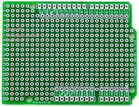
The power connector is just a generic one that you usually find for 12V. I didn't have anything particular in mind as most of them will fit providing they have tabs in what look like the right places. They are generally sized by the diameter of the inner pin and, for this size, are usually 2.1mm or 2.5mm. Of course, it helps if you know what power supply you are going to plug into it. :) Over on this side of the pond I'd probably fit a 2.1mm. The barrel diameter is usually 5.5mm in both cases. You should be able to find them at any component supplier, even small ones. Also on ebay and AliExpress. Mick I'm open to most any connector, my Long game Plans is to power them with 18650 Batteries to R/C LiPo Batteries, I'm just more concerned with getting the correct one for the PCB. Also I am a dumb American and worse than That I'm a Dumb Texan, so we NEVER use the Metric system, we work on the Banana Unit of Measurement There are several things about that board that I don't think I'd do in the same way now. The first is that I'd lose all the mechanical compatibility with the Arduino. It's such a poor mechanical design that it almost makes me want to cry. ......... Of course it's not compatible with Arduino "hats" but as you can't run Arduino code on it anyway that's not really a great loss. . I must Take some or all responsibility I really did and do want a Mechanically compatible because of all the robotic Kits and other Projects that can be 3D Printed and the cool thing is the ready Protoboards availability !  I may be Vulgar, but , while I'm poor, I'm Industrious, Honest, and trustworthy! I Know my Place |
||||
| Mixtel90 Guru Joined: 05/10/2019 Location: United KingdomPosts: 6783 |
Unfortunately the barrel jack connectors were never made in inches AFAIK. :) If you don't fit the socket you can still power the board from VIN and GND to feed the regulator, but there is no reverse polarity protection. You will need at least 6.2V (or 6.6V if you use the socket) to get 5V out of the regulator. If you leave off the socket, D1, C1 and regulator you can power the board directly into 5V and GND (n. This goes directly into the Pico so you can go as low as 1.8V and up to 5.5V if you use the switching supply (don't bridge the 3EN pads). That makes it ideal for a 3V7 lithium cell. You'll also lose about 0.4V in D2, which gives polarity protection, but you can short it out if you want to take the risk. Mick Zilog Inside! nascom.info for Nascom & Gemini Preliminary MMBasic docs & my PCB designs |
||||
| Volhout Guru Joined: 05/03/2018 Location: NetherlandsPosts: 4223 |
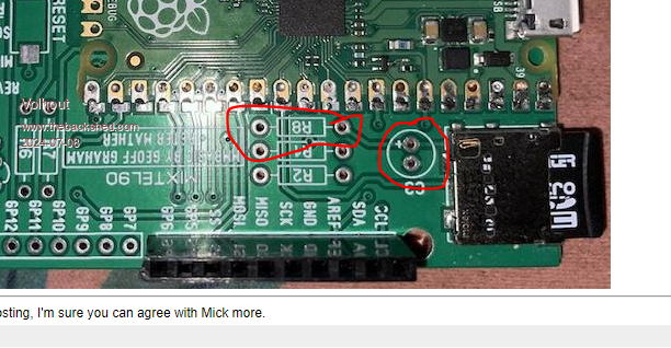
@Rickard, You need R8 and C3 for the SD card to work.  Volhout PicomiteVGA PETSCII ROBOTS |
||||
| Rickard5 Guru Joined: 31/03/2022 Location: United StatesPosts: 463 |
@ Volholt Last night I populated this board with what I had including the components you pointed ou snd still NO JOY, when I get back this afternoon I'm going to start all over and try again with a new PCB and Pico :) I may be Vulgar, but , while I'm poor, I'm Industrious, Honest, and trustworthy! I Know my Place |
||||
| Mixtel90 Guru Joined: 05/10/2019 Location: United KingdomPosts: 6783 |
Before you put stuff on the new board check for track continuity and shorts on all tracks connected with the uSD card. That way, if you have to check again later, you'll have a better idea on where to look for a fault. The board looks fine to me on SL6, but you can get bad etches now and again. If you put bits of component lead through the 1mm dia. holes in pads 1 and 21 it will help you line up the Pico properly. Just dab solder them to either the top of the Pico or the bottom of the PCB. You can take them out later when you make the proper joints. Don't attempt to solder down the holes in the pico if surface mounting it, solder to the inside of the castellations on the outside edge. Some of the joints don'y look too good to me. . Edited 2024-07-10 00:56 by Mixtel90 Mick Zilog Inside! nascom.info for Nascom & Gemini Preliminary MMBasic docs & my PCB designs |
||||
| Rickard5 Guru Joined: 31/03/2022 Location: United StatesPosts: 463 |
@ Mick Thanks Buddy, I'm on it I'm gonna start on it sometime before 5:00 PM tonight (Amazon Prime Promises) I may be Vulgar, but , while I'm poor, I'm Industrious, Honest, and trustworthy! I Know my Place |
||||