|

|
Forum Index : Microcontroller and PC projects : Controlling a Dimplex 9L Desiccant Dehumidifer (GDDEKD9)
| Author | Message | ||||
| Technophiliac Regular Member Joined: 18/12/2020 Location: New ZealandPosts: 92 |
Thinking about how to swtich referred dehumidifier ("DH") on and off via relay (and its control chain) with the objective running the DH only when the humidity is above some level (Maybe 55%) and when the time of use power is cheap, that is it won't run during peak power periods. Thing is it does not have a simple main on / off switch, rather turing it off involves pushing a button, and then it times out some turn off cycle, and does not like being turned off by pulling the plug, also has its own auto function which sort of works humidity wise but does not have the timing logic incorporated. Circuits not been found to date but by chance I found a site with pics of part, there are two boards, the switch board looks like this:  The On/Off switch is marked in the middle (!) I am guessing this is a simple push to make spst switch and that I can add a wire to each side of the switch and connect to an external relays contacts. Its easiest for me to have relay on when DH is on, and relay off when DH is off. With this approach I need to somehow trigger the relay to flick on and off for a moment to toggle on and off which might do it (assumptions excepted!). Maybe someone here has knowledge of the likely switching logic and is there a better way to turn the DH on and off remotely? Davo, Wellington. You can have it perfect, on time, and at the best price. Choose any two. |
||||
| Technophiliac Regular Member Joined: 18/12/2020 Location: New ZealandPosts: 92 |
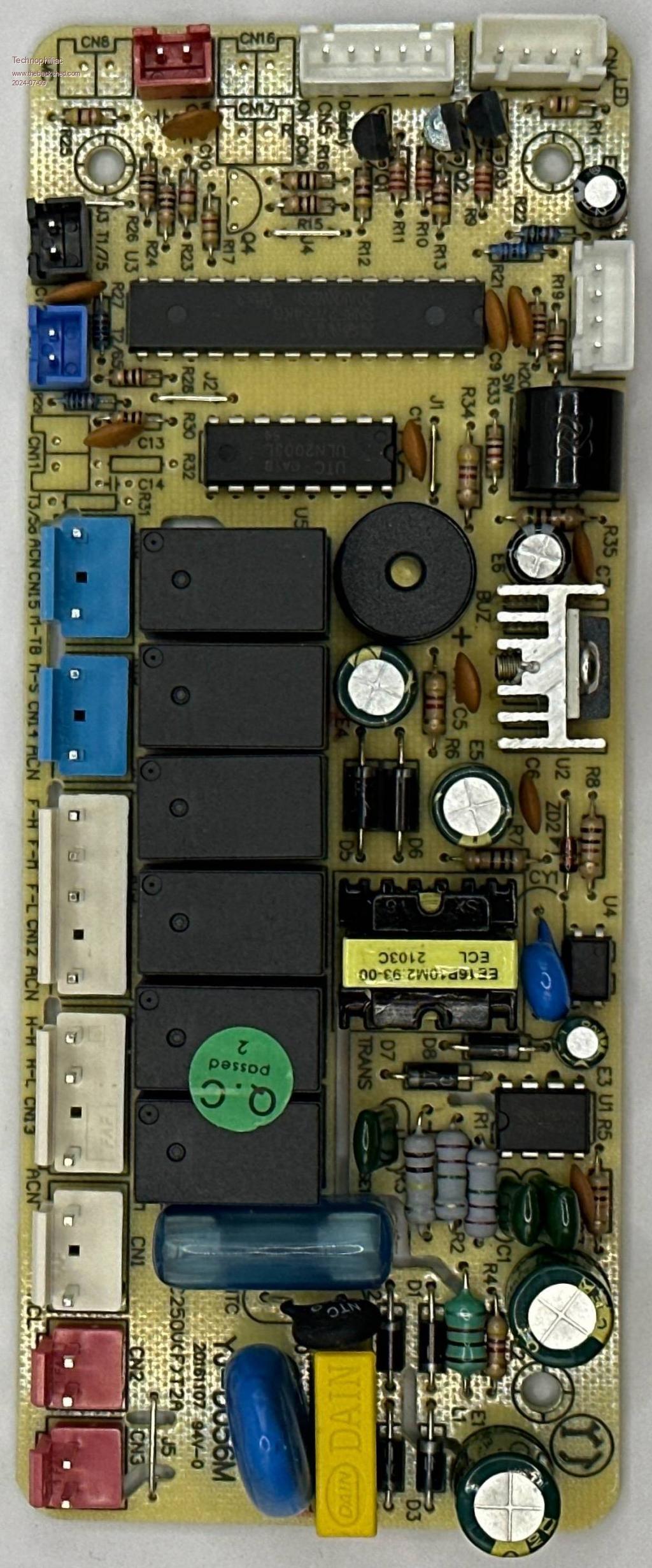
 Fwiw this is the main board that interfaces if it helps anyone at all. Davo, Wellington. You can have it perfect, on time, and at the best price. Choose any two. |
||||
| Volhout Guru Joined: 05/03/2018 Location: NetherlandsPosts: 4223 |
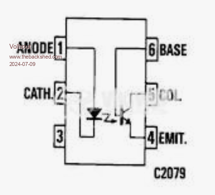
Hi Technophiliac, Pushbutton switches with a double function (1=ON, 2=OFF) are a pain.... You can never be sure what the units is actually doing. So you need a feedback. Looking at the PCB, the pushbutton switch could switch logic level (an input the the MCU). Use a multimeter, to find voltage + and - on the pushbutton switch. Then connect an optocoupler output accross the switch (+=C, -=E), you can drive the optocoupler LED safely from your external electronics, without affecting the DH. Any optocoupler type will do (PC817, TIL111, etc...). This is optocoupler 1 The feedback should give you information if the DH is ON or OFF. Maybe the DH has a indicator LED that shows it is ON or OFF. OR maybe one of the relays on shown PCB is ON when the DH is ON (and OFF when the DH is OFF). This detective work, since you have no service manual. IF it is one of the relays, it is simple. Just use a second optocoupler (optocoupler 2) parallel to the relay coil. The LED side connects to the relay coil (+=A, -=K via a resistor 1k). Don't omit the resistor !! K stands for Kathode/Cathode The opto coupler output can safely be used by your external electronics. Run these 4 wires (optocoupler 2 output C/E, optocoupler 1 input A/K) to a single connector (DB9/DIN/whatever you want to use) to your external electronics. In case you use an optocoupler that has a B(base) connection on one of the pins. Do not connect that B connection. TIL111  Volhout Edited 2024-07-09 17:08 by Volhout PicomiteVGA PETSCII ROBOTS |
||||