|

|
Forum Index : Microcontroller and PC projects : Colour Maximite 2 Gen2
| Author | Message | ||||
| fmafma Newbie Joined: 30/06/2023 Location: FrancePosts: 31 |
Hi! Where can I find the files to cut the front and rear of the box of the CMM2 Gen2, as seen here: https://geoffg.net/Images/Maximite/G2_FrontTopView.jpg Thanks, Edited 2024-06-28 00:26 by fmafma Frédéric |
||||
Grogster Admin Group Joined: 31/12/2012 Location: New ZealandPosts: 9306 |
Bonjour. I designed those.  They are made as "PCB's" at a PCB house such as JLC, not 3D printed or routed. CMM2_G2_NO LOGOS.zip These are the panels you see in the photos, but they have my Rictech logo and website removed. They are therefore generic, and public-domain and anyone is free to use them to make panels for their CMM2's. Note that you USUALLY have to explain to the PCB house what you are doing, or they will query why there are no copper layers and you are unable to "Weld" them I just insert a note in the order(in the comments box) - translated to Chinese via Google Translate - saying: "Black soldermask ink both sides, cannot weld. Project panels only." With that comment in the order, they normally don't question them, and will accept the order. Let us know how you get on. Au revoir. Smoke makes things work. When the smoke gets out, it stops! |
||||
| fmafma Newbie Joined: 30/06/2023 Location: FrancePosts: 31 |
Thank you very much! I'll probably have them cut/engraved with a laser cutter, or maybe with both a laser cutter and a vinyl cutter. Best, Frédéric |
||||
| Mixtel90 Guru Joined: 05/10/2019 Location: United KingdomPosts: 6783 |
Another way might be to keep the copper on but simply etch it off for a couple of mm right round the edge of the panel. It depends on the enclosure, some seem to be able to accept the copper anyway, I've got away with that in the past. Or you could leave the copper on but drop a board thickness. The copper has its uses in that it makes sure the panels are opaque. Mick Zilog Inside! nascom.info for Nascom & Gemini Preliminary MMBasic docs & my PCB designs |
||||
Grogster Admin Group Joined: 31/12/2012 Location: New ZealandPosts: 9306 |
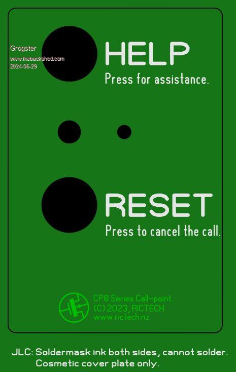
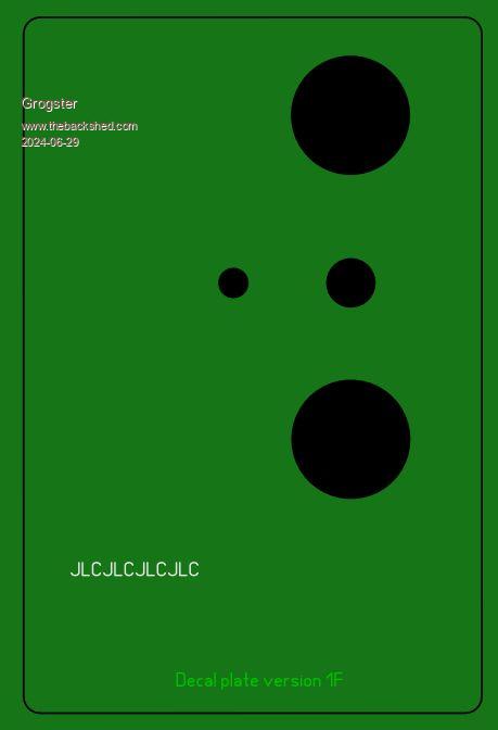
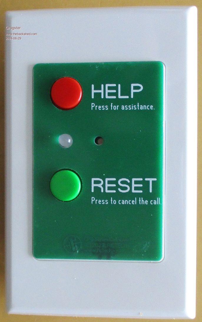
On my latest "Decal plate", I actually have my company logo etc, as copper on the top copper layer, and also something on the bottom layer, both covered with soldermask. Then, they never ask, as they have all the layers they expect.  This also keeps my company logo etc on the plate, but in a discrete fashion so as not to stick out like a sore thumb.   I get these made in 0.6mm board, so they are nice and thin, and I simply glue them to the top of the(already drilled) wall-plate using a thin smear of silicone sealer. I use the silicone sealer, as it allows you to "Slide" the decal plate around on the top of the wall-plate, to get it centered correctly. Once the silicone cures overnight, they are stuck firm, but still reasonably easy to pop off if you ever need to.   Smoke makes things work. When the smoke gets out, it stops! |
||||
| Mixtel90 Guru Joined: 05/10/2019 Location: United KingdomPosts: 6783 |
Those look good. :) Doing your logo like that is very neat. Mick Zilog Inside! nascom.info for Nascom & Gemini Preliminary MMBasic docs & my PCB designs |
||||
| lizby Guru Joined: 17/05/2016 Location: United StatesPosts: 3150 |
Nice. Thanks for the tip. PicoMite, Armmite F4, SensorKits, MMBasic Hardware, Games, etc. on fruitoftheshed |
||||