
|

|
Forum Index : Microcontroller and PC projects : CMM1.5 full design files
| Author | Message | ||||
| matherp Guru Joined: 11/12/2012 Location: United KingdomPosts: 9110 |
The CMM1.5 is a platform for running the PicoMiteVGAUSB software. Attached are all the design files to allow anyone to build this. The box is the MULTICOMP MCRM2015S. Price for 5 boards fully complete and ready to run from JLC is £80.20 + shipping and any country dependent taxes. The push button on the volume control is non-latching so it can't be used for an on-off switch. Instead it is connected to GND and GP0 allowing it to be used as a user input for a program. To install the firmware connect a USB-A to USB-A cable to the USB-A socket while holding down the "BOOT" switch. Copy the PicoMiteVGAUSB V5.09 firmware .uf2 file to the disk drive created by the RP2040. Then remove the USB-A cable and connect a USB-C for a console. Type OPTION RESET CMM1.5 and you are then fully configured Dxf and stl files for the box ends CMM1.5ends.zip Gerbers CMM1.5.zip BOM and pick and place files BOM_CMM1.5.zip Schematic 3848545a-2bf6-4683-863d-df975790c97e.pdf EasyEDA design file CMM1.5easyeda.zip 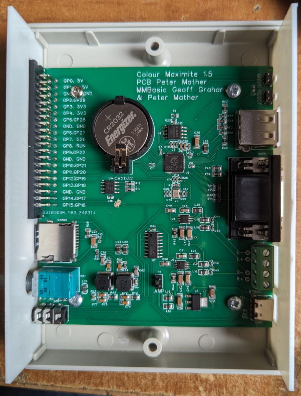   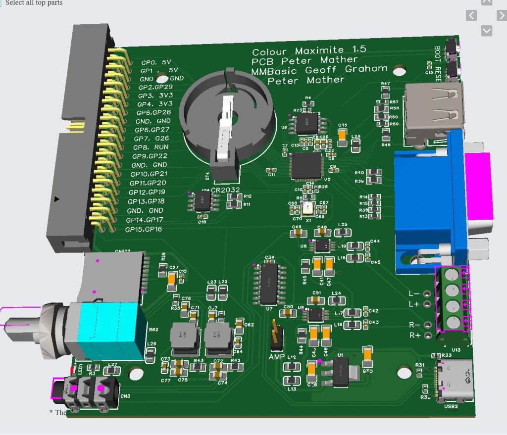 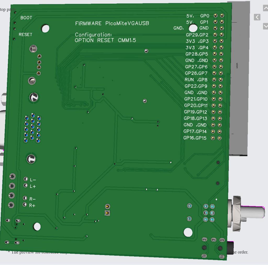 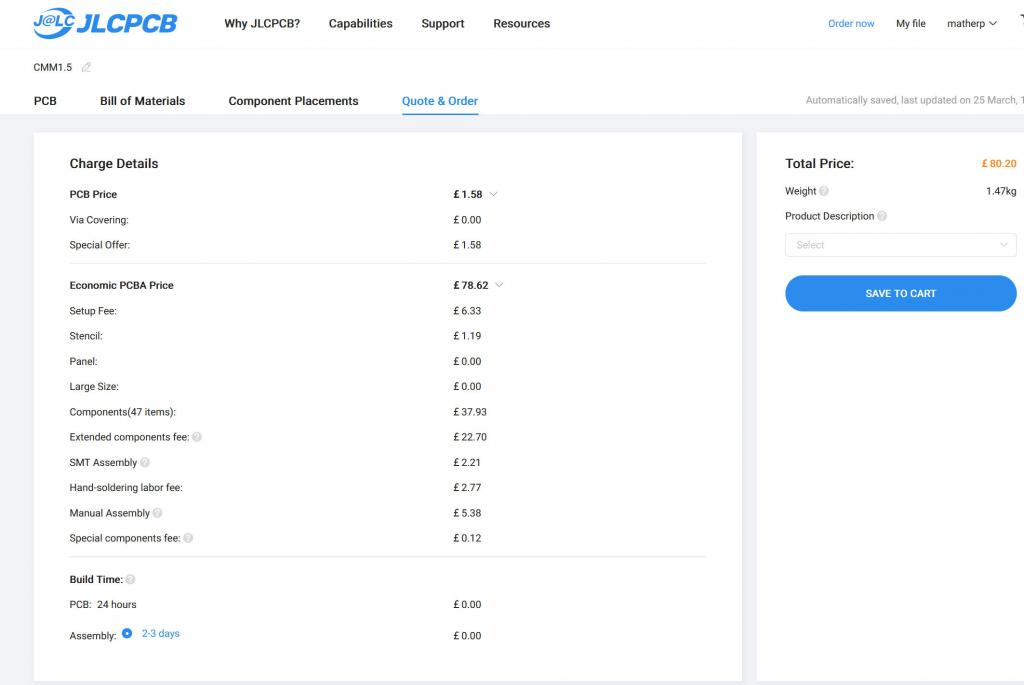 Edited 2024-03-26 02:02 by matherp |
||||
| Volhout Guru Joined: 05/03/2018 Location: NetherlandsPosts: 4223 |
Hi Peter, JLC has removed the top copper cooling of U1. This may not be a huge issue, but the board is not the same as the 3D simulation files you included in this same post. Volhout P.S. You should not eat cookies while making photographs.......DS3231 Edited 2024-03-26 17:52 by Volhout PicomiteVGA PETSCII ROBOTS |
||||
bigmik Guru Joined: 20/06/2011 Location: AustraliaPosts: 2914 |
Gday Peter, All, Something I have noticed when using a HUB (a compatible one of course) If I plug a Mouse in (and nothing else) I get a connected report, upon removing the mouse I always get a disconnected report. However, If I plug a Keyboard in (and nothing else) I get a connected report, upon removing the keyboard I never get a disconnected report. This works with keyboard directly to the "1.5 PicoVGA-USB" with no hub in between. Another funny, if a keyboard is plugged in first and then a mouse is plugged in I get no mouse connected reports. This also carries to if I plug the mouse in first then the keyboard, removing either does not report a disconnect. If both are plugged in before power up (or use RESET) then both are detected but none will report a disconnect) Is this a limitation of the Tiny-USB code or is it something else? If it is a limitation of tiny-USB then its workable to have them plugged up before a power up or reset but it does seem strange that the mouse detects every time until a keyboard is plugged in. I have tried 3 different keyboards and they all do the same. BTW, I have VGA-Pico-USB ver 5.09.00RC1 Kind Regards, Mick Mick's uMite Stuff can be found >>> HERE (Kindly hosted by Dontronics) <<< |
||||
Grogster Admin Group Joined: 31/12/2012 Location: New ZealandPosts: 9306 |
Trying to get JLC to 3D print the end-panels for the box, but no matter WHAT type of 3D printing I select(material or technology), it is rejected as being too small. Peter? 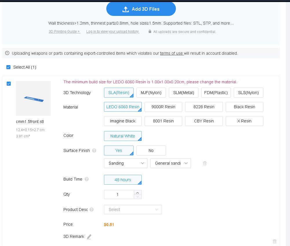 Smoke makes things work. When the smoke gets out, it stops! |
||||
| matherp Guru Joined: 11/12/2012 Location: United KingdomPosts: 9110 |
No idea. I printed myself. You could convert the DXF files to Gerbers and get them made as pcbs |
||||
bigmik Guru Joined: 20/06/2011 Location: AustraliaPosts: 2914 |
Hi Grogster, All, It looks like a face plate, I agree with Peter, get them done as PCBs Here is a scan of one I have just had made in the last month.  Kind regards, Mick (The Big one) EDIT*** I got this one made in 0.8mm but of course you can get any size that they do PCBs in. Mik . Edited 2024-05-21 16:54 by bigmik Mick's uMite Stuff can be found >>> HERE (Kindly hosted by Dontronics) <<< |
||||
| Volhout Guru Joined: 05/03/2018 Location: NetherlandsPosts: 4223 |
You selected 0.15cm thick, and 0.2cm (2mm) thick is the minimum they offer. You could redesign the panels to be 0.2cm thick, and have the edges slimmed down to 0.15cm. Volhout PicomiteVGA PETSCII ROBOTS |
||||
Grogster Admin Group Joined: 31/12/2012 Location: New ZealandPosts: 9306 |
Thanks.  Can anyone recommend a program to convert the DXF's to GERBER's? I cannot import DXF's to my PCB program. I'd actually PREFER to do them as black PCB's, but I could not import the DXF files. Perhaps if I can get a little prod in that direction, I can then take it from there.  Smoke makes things work. When the smoke gets out, it stops! |
||||
Grogster Admin Group Joined: 31/12/2012 Location: New ZealandPosts: 9306 |
I didn't.  I just uploaded the files, and JLC decided about the thickness - I had no choice on that. Anyway, I would PREFER to do them as PCB panels, just as I did for the CMM2_G2's, so I will pursue that option now.  Smoke makes things work. When the smoke gets out, it stops! |
||||
bigmik Guru Joined: 20/06/2011 Location: AustraliaPosts: 2914 |
Grogster, It wouldn’t be difficult to just redesign them in your PCB program. A note on cut-outs though. DEXpcb creates a seperate Gerber file for the cutout areas. JLC used to be quite happy with this and do the cutouts as designed. They have changed something now and require that the cutouts be on the border Gerber file. They will still do them with a seperate cutouts.gbr file but NOT automatically. You need to request confirmation of the manufacturing and add a comment about the Gerber for cutouts. Before they start you can see the output and if the cutouts are not White then they will not be cutout of the PCB. If they are white then confirm the manufacture and all ‘should’ be OK. BTW, JLC are now able to do full colour PCBs and have an introductory offer BUT the design has to be created using their EASY-EDA program and I don’t have a desire to learn a new program. Besides the cost is quite considerable compared to the peanuts price of the standard process. This would make for really nice face plates. Regards, Mick. . Edited 2024-05-21 17:35 by bigmik Mick's uMite Stuff can be found >>> HERE (Kindly hosted by Dontronics) <<< |
||||
| Mixtel90 Guru Joined: 05/10/2019 Location: United KingdomPosts: 6783 |
When I want cut-outs from JLCPCB I put them on the border layer and also put a rough cross in the middle of each on the same layer. It's not been queried yet and has worked every time. :) I had a go with Easy EAD and it's pretty good. Worth persevering with for anything of any complexity. Mick Zilog Inside! nascom.info for Nascom & Gemini Preliminary MMBasic docs & my PCB designs |
||||
bigmik Guru Joined: 20/06/2011 Location: AustraliaPosts: 2914 |
Hi Mick, All, With Dex, I can’t dictate what gerber layer cutouts are placed in. I asked the creator of Dex if he could support adding cutouts to the border gerber but he refused stating that it is not standard to do so, so he won’t add that support. I can get over the problem as I itemised above but it is a PiTa, and as I said JLC used to automatically action the cutouts when they were in their own gerber file. I tried a program called GerbMerge and it would combine two gerber files into one but it would lose registration to the other files so was of no use. Does anyone know if there is a method of merging 2 gerbers into one that keeps the registration used in both when the merged one is exported? Regards, Mick . Mick's uMite Stuff can be found >>> HERE (Kindly hosted by Dontronics) <<< |
||||
Grogster Admin Group Joined: 31/12/2012 Location: New ZealandPosts: 9306 |
Yes, when I did the panels for the CMM2 and G2, they were done as blank black PCB's with silkscreen only. They look great, and are easy etc. I suppose I can just draw up my own ones. I figured the DXF file would speed that along, but perhaps not!  I have to do the new CMM2 panels too, so I suppose I could just settle into doing them both at the same time, while I am thinking about it. Yes, I put all the cutouts on the "Outline Layer" in Sprint Layout, and they always came back fine from JLC. I did have to put a note in the order(translated to Chinese) saying these were just panels, not-solderable, no copper, just black ink and silkscreen, otherwise they did tend to question why there was no copper etc. Smoke makes things work. When the smoke gets out, it stops! |
||||
Grogster Admin Group Joined: 31/12/2012 Location: New ZealandPosts: 9306 |
Can anyone suggest any other links for the cases for this board? I can get them from element14(NZ/AUS version of Farnell UK), but they are $16 a box, which is twice the price of the CMM2 case, and that one is larger! I'll buy them at $16 a case if I have to, but perhaps other members have links to a supplier at a better price? Mouser and DigiKey don't seem to know anything about that part number. Smoke makes things work. When the smoke gets out, it stops! |
||||
bigmik Guru Joined: 20/06/2011 Location: AustraliaPosts: 2914 |
Grogster, All, Is it the same as the CMM2 case ie. HB5970 ? If so >>> Jaycar <<< has them for $7.95ea. Regards Mick EDIT *** Jaycar NZ has the for $7.10NZ in QTY 10 Mik . Edited 2024-05-22 12:35 by bigmik Mick's uMite Stuff can be found >>> HERE (Kindly hosted by Dontronics) <<< |
||||
Grogster Admin Group Joined: 31/12/2012 Location: New ZealandPosts: 9306 |
Yes, those are the ones I get from Jaycar, for the CMM2. The CMM1.5 is a SMALLER case then that one, so I can't use it.  I need the one that Peter described at the top of this thread. Smoke makes things work. When the smoke gets out, it stops! |
||||
| Mixtel90 Guru Joined: 05/10/2019 Location: United KingdomPosts: 6783 |
https://www.ebay.co.uk/p/1042770132 https://octopart.com/mcrm2015s-multicomp-7505540 https://www.newark.com/multicomp/mcrm2015s/enclosure-desktop-case-with-pcb/dp/74M3045 Mick Zilog Inside! nascom.info for Nascom & Gemini Preliminary MMBasic docs & my PCB designs |
||||