|

|
Forum Index : Microcontroller and PC projects : Does this work as an audio filter?
| Author | Message | ||||
| matherp Guru Joined: 11/12/2012 Location: United KingdomPosts: 9115 |
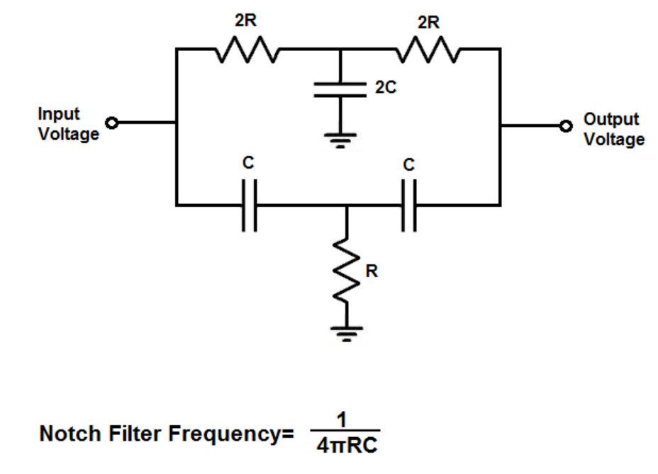
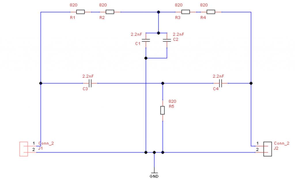
There is an interesting video on youtube in which the presenter describes the two-tee notch filter  If I understand it properly and have calculated correctly component values of 820 ohm and 2.2nF should give a "notch" at close to 44100Hz with just two common component values. Could one of our SPICE gurus please model this for me. I've attached the protel net list if it helps  [ J1 SIP2 Conn_2 ] [ J2 SIP2 Conn_2 ] [ C1 package name for PCB layout 2.2nF ] [ C2 package name for PCB layout 2.2nF ] [ C3 package name for PCB layout 2.2nF ] [ C4 package name for PCB layout 2.2nF ] [ R5 AX3_1N 820 ] [ R1 AX3_1N 820 ] [ R2 AX3_1N 820 ] [ R3 AX3_1N 820 ] [ R4 AX3_1N 820 ] ( GND C1-2 C2-2 J1-2 R5-2 J2-2 ) ( N000002 J1-1 C3-1 R1-1 ) ( N000003 C3-2 R5-1 C4-1 ) ( N000004 R1-2 R2-1 ) ( N000005 R2-2 R3-1 C2-1 C1-1 ) ( N000006 R3-2 R4-1 ) ( N000007 R4-2 C4-2 J2-1 ) Edited 2024-02-18 19:09 by matherp |
||||
| stanleyella Guru Joined: 25/06/2022 Location: United KingdomPosts: 2129 |
Would the existing filter be better? harmonics of the carrier, dunno? |
||||
| matherp Guru Joined: 11/12/2012 Location: United KingdomPosts: 9115 |
This one is much cheaper if it works - all JLC "basic" components |
||||
| stanleyella Guru Joined: 25/06/2022 Location: United KingdomPosts: 2129 |
it's a notch not a bandpass filter. nothing over 12khz would be realistic imho. stan I bought a pack of 5 inductors £3 free p&p Edited 2024-02-19 02:51 by stanleyella |
||||
| Mixtel90 Guru Joined: 05/10/2019 Location: United KingdomPosts: 6787 |
Volhout's inductor filter is a low-pass at a bit below 44.1kHz. It's very steep (because it's an inductive resonant system) and virtually kills everything from 44.1kHz upwards, while passing everything below about 16kHz. A notch filter is centered on one particular frequency and will attempt to kill that completely. However, it probably won't take out the harmonics. Centered on 44kHz it would pass 88kHz and 1.32MHz etc. I don't think it would be ideal in this instance unless followed by a low-pass type to take out the harmonics. Unfortunately I'm no expert on filters (or Spice) - Volhout is your guy. :) Mick Zilog Inside! nascom.info for Nascom & Gemini Preliminary MMBasic docs & my PCB designs |
||||
| matherp Guru Joined: 11/12/2012 Location: United KingdomPosts: 9115 |
My understanding was that Volhout's design is also a notch because he was concerned about 48K PWM rates not being suppressed as well as 44100 |
||||
| Turbo46 Guru Joined: 24/12/2017 Location: AustraliaPosts: 1611 |
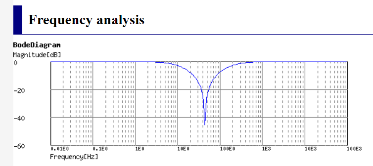
I went to this site and entered the R and C values and got this result:  I think the result is similar to Volhout's LC filter but it needs a low pass filter before it as in Volhout's circuit to reduce the higher frequencies. Bill Keep safe. Live long and prosper. |
||||
| hitsware2 Guru Joined: 03/08/2019 Location: United StatesPosts: 713 |
Isn't the purpose here to rid audio of clock noise ? my site |
||||
| Mixtel90 Guru Joined: 05/10/2019 Location: United KingdomPosts: 6787 |
&You may be right, Peter. As I said, I'm not an expert at filters. I *think* the output cap to ground forms part of the low pass though. Mick Zilog Inside! nascom.info for Nascom & Gemini Preliminary MMBasic docs & my PCB designs |
||||
| stanleyella Guru Joined: 25/06/2022 Location: United KingdomPosts: 2129 |
end of the day are you happy with the filter in the manual, which seems to have used preferred value caps. it was never supposed to be "hi fi" but now flac files?? anyone tried an opposing carrier to cancel out the audio carrier and leave the audio? |
||||
| Turbo46 Guru Joined: 24/12/2017 Location: AustraliaPosts: 1611 |
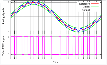
An RC filter is needed to recover an AC audio signal from the PWM signal and to roll off the higher frequencies. However it will still contain remnants of the PWM signal. Some people consider that undesirable.  The purpose of the Twin T filter or the LC filter is to remove, or greatly reduce, the 44.1kHz PWM carrier part of the audio. Earlier designs did not include the notch filter. Bill Keep safe. Live long and prosper. |
||||