|

|
Forum Index : Microcontroller and PC projects : CNC Speed Monitor
| Author | Message | ||||
| Volhout Guru Joined: 05/03/2018 Location: NetherlandsPosts: 4233 |
OA47, If the shaft rotates at 20000rpm (20000/60=333Hz) and the fan at that shaft has 10 blades, the frequency atthe opticla sensor will be 10x333=3.3kHz. The period of that signal will be 300us, best case 150us ON, 150us OFF. But since fan blades like to cover most of the surface for effciency, it will be more 100us ON, 200us OFF. Most IR receivers (modulated 38kHz) are designed for ON-OFF timing between 5ms and 500us. It is possible the fan blades cannot be reliably detected with these 38kHz IR receivers. For IR receivers I would suggest use the shaft, not the fan blades. But I still would suggest the hall sensor with (2) magnets in a dusty environment, or a single magnet on top of the shaft (in which case it must be positioned correct to create a field change). There are small 3mm diameter "supermagnete" that should do the job with some epoxy glue. where to buy You can also buy "ring magnet" with axial magnetization, that you can simply "glue" around the shaft, so you have no unbalance. The picture below shows where to select axial magetisation, and shows the smallest of them, but there are MUCH larger ones in this list. Volhout Edited 2024-02-06 19:34 by Volhout PicomiteVGA PETSCII ROBOTS |
||||
| TommySr Newbie Joined: 01/02/2024 Location: United StatesPosts: 1 |
The Nano 33 BLE comes with a 9 axis inertial measurement unit and, a magnetometer with 3-axis resolution and, a 32-bit ARM® Cortex®-M4 CPU running at 64 MHz and, is low cost. because it's an electric motor could the magnetometer mounted next to the motor be used for motor commutation, or even an accelerometer could be used to measure the motor vibration which could be proportional to it's rpms. adding an encoder for speed feedback seems to be most common approach. a US DIGITAL encoder list max rpm of 60000. if nothing else it would be fun to try. Edited 2024-02-06 20:47 by TommySr |
||||
| PhenixRising Guru Joined: 07/11/2023 Location: United KingdomPosts: 858 |
@Volhout  |
||||
| PhenixRising Guru Joined: 07/11/2023 Location: United KingdomPosts: 858 |
@TommySr I don't think that the project is that ambitious. SimpleFOC now runs on the Pico and that would commutate the motor and provide all kinds of feedback. Not gonna happen here. |
||||
| Mixtel90 Guru Joined: 05/10/2019 Location: United KingdomPosts: 6787 |
*If* the motor had an encoder of any sort it would be trivial. :) Strobe looking at the fan blades. Be careful though - they'd appear stopped! A PicoMite is quite suitable to PWM a suitable LED. I'm not sure *why* you want to know the speed. If it's to set it then a strobe would be great - have preset flash rates. I can't see any need to want an accurate reading anyway, as it will change continually on load. Mick Zilog Inside! nascom.info for Nascom & Gemini Preliminary MMBasic docs & my PCB designs |
||||
| OA47 Guru Joined: 11/04/2012 Location: AustraliaPosts: 926 |
I will try the optical route firstly as it will be the easiest. Here is my initial code for assessment. ' IR TACHOMETER PROGRAM FOR MICROMITE ' IR LED POWERED ON ' IR RECEIVER CONNECTED TO PIN 16 ' INITIALISE PINS FOR 2 LINE LCD LCD INIT 2,3,4,5,23,24 SetPin 16,FIN 'IR RECEIVER LCD 1,3,"IR TACHOMETER" LCD 2,10," RPM" Do Print Pin(16);" Hz" LCD 2,1,Str$(Pin(16)*60) Pause 500 LCD 2,1," " Loop 0A47 |
||||
TassyJim Guru Joined: 07/08/2011 Location: AustraliaPosts: 6098 |
Instead of tape, why not paint half the shaft mat black? It should stay on longer... Jim VK7JH MMedit MMBasic Help |
||||
| OA47 Guru Joined: 11/04/2012 Location: AustraliaPosts: 926 |
Matt black paint it is.  0A47 |
||||
| OA47 Guru Joined: 11/04/2012 Location: AustraliaPosts: 926 |
Thinking about this, I believe the speed of the spindle is controlled by the voltage (100V=20000 rpm) and if I can get a reliable read of the speed with the IR tachometer then I could just monitor the motor voltage and convert it to display RPM. 0A47 |
||||
| Mixtel90 Guru Joined: 05/10/2019 Location: United KingdomPosts: 6787 |
Is it a simple DC motor or a special brushless one? If so there may be a speed control input to the motor. You could simply read that control voltage. Mick Zilog Inside! nascom.info for Nascom & Gemini Preliminary MMBasic docs & my PCB designs |
||||
| OA47 Guru Joined: 11/04/2012 Location: AustraliaPosts: 926 |
As far as I know, there is a PWM output from the GRBL controller that is converted to 0-5V and fed into the motor power supply to control the spindle speed. 0A47 |
||||
| OA47 Guru Joined: 11/04/2012 Location: AustraliaPosts: 926 |
Here is the code with a little bit of averaging. ' IR TACHOMETER PROGRAM FOR MICROMITE ' IR LED POWERED ON ' IR RECEIVER CONNECTED TO PIN 16 ' INITIALISE PINS FOR 2 LINE LCD LCD INIT 2,3,4,5,23,24 SetPin 16,FIN 'IR RECEIVER Dim Spin,I LCD 1,3,"IR TACHOMETER" LCD 2,10," RPM" Do Spin=0 For I = 1 To 10 Spin = Spin + Pin(16) Next I Print Spin/10;" Hz" LCD 2,1,Str$(Spin*6) Pause 500 LCD 2,1," " Loop 0A47 |
||||
| Mixtel90 Guru Joined: 05/10/2019 Location: United KingdomPosts: 6787 |
The 5V control signal could be measured to give an indication of the speed it's being told to run at. *If* there is load compensation within the motor electronics there'll be a feedback signal compared with the 5V control, so the 5V signal going in will be pretty accurate, even on load. The mark/space of the PWM could be measured but it's more fiddly and you don't really gain anything. It'll be interesting to see how this goes. :) Mick Zilog Inside! nascom.info for Nascom & Gemini Preliminary MMBasic docs & my PCB designs |
||||
| OA47 Guru Joined: 11/04/2012 Location: AustraliaPosts: 926 |
This will be the log term aim as it seems the most appropriate and tidy way of doing it but I need the IR tacho to give a consistent and reliable reference. I am using the 3 terminal 38Khz IR receiver but initially I have been powering on the transmit LED fully from 5V via a resistor. This set up gives results but can be inconsistent I did try to modulate the transmit LED at 38Khz via the PWM output and a BC338 but it doesn't get picked up by the receiver. When I looked at the LED output through a camera the output of the LED is very dull. Should I need to modulate the transmit LED at 38Khz to get a reliable output from the IR receiver? 0A47 |
||||
| Mixtel90 Guru Joined: 05/10/2019 Location: United KingdomPosts: 6787 |
That's something I've never tried, but I doubt if the receiver will give much unless the LED is modulated at 38kHz. That's the whole point of the system, it makes the receiver insensitive to surrounding light. As Volhout has pointed out, a 38kHz modulated system might not work in this application because the device to be sensed is moving so rapidly. Mick Zilog Inside! nascom.info for Nascom & Gemini Preliminary MMBasic docs & my PCB designs |
||||
| phil99 Guru Joined: 11/02/2018 Location: AustraliaPosts: 2135 |
Some IR receivers require a 10kΩ pullup on the output pin and Vcc needs a 100nF to 10µF capacitor to ground at the pins. 38kHz (+/-2kHz) modulation is essential. Max. drive current will depend on the IR LED but 50mA for a continuous square wave is typical. Forward voltage drop is about 1.1V so for a 5V supply use 75Ω in series. A NE555 or any general purpose transistor with 3.3kΩ base resistor should work. Just tested one on a drill with 10 stripes around the chuck and got 200Hz = 12000 RPM for a shaft with 1 stripe. Place the IR LED so that the receiver doesn't get any direct signal from it. Direct IR illumination will swamp the reflected signal. I have them side by side with a small barrier between |
||||
| OA47 Guru Joined: 11/04/2012 Location: AustraliaPosts: 926 |
Phil, I am using a BC338 transistor base fed by a 1K resistor from the PWM pin on the micromite and an 82R resistor feeding the LED from 4.5V to the collector with the emitter grounded. 0A47 |
||||
| Volhout Guru Joined: 05/03/2018 Location: NetherlandsPosts: 4233 |
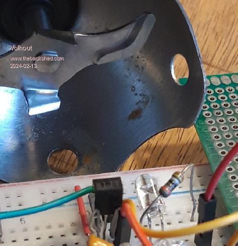
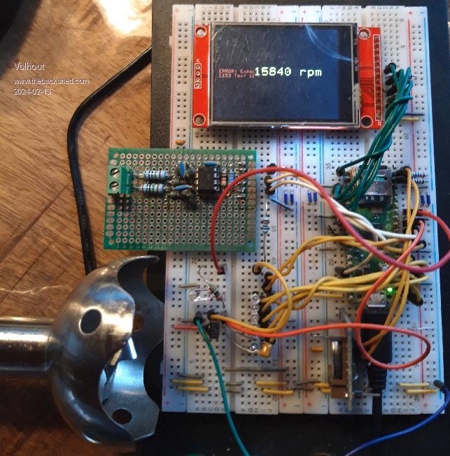
Hi OA47, I tested it, and it works amazingly good. I used a IR LED from an old IR remote control, and connected it to a 38kHz PWM output through a 330ohm resistor, You do not need to drive the LED hard, since it is designed for 7 meter (remote to TV) range, and we need only few cm. I used a (old) 5V IR sensor from a set top box. The output of these sensors is "open drain", so I added a 10k resistor to +3.3V from it's output. I faced both IR LED (transparent 5mm LED in below photo) and IR sensor (the small black item) roughly towards the blades of a kitchen blender. Since the IR sensor has automatic gain control and AM demodulation, it will see the blades nicely.  Using the blender turbo speed, I could achieve 15800 rpm. See below simple test program. My LED is connected to GP10 (PWM5A), the frequency is measured at GP9. Ignore the breadboard, it has circuits to debug PIO, RTCm, mains monitor and many more. I just added this for test. 'test for rpm measurement SetPin gp10,pwm '38kHz out SetPin gp9,fin 'pulse input from IR receiver 'generate IR stream PWM 5,38000,50 'freq to rpm blades=2 conversion=60/blades Do r=Pin(gp9)*conversion Text 100,100,Space$(12),,4,2 Text 100,100,Str$(r,4,0)+" rpm",,4,2,RGB(yellow) Pause 200 Loop  Regards, Volhout P.S. Most TV remote IR LED's are designed for 500mA peak. We only need 5mA or so for this short distance. Edited 2024-02-13 18:12 by Volhout PicomiteVGA PETSCII ROBOTS |
||||
| PhenixRising Guru Joined: 07/11/2023 Location: United KingdomPosts: 858 |
@Volhout  |
||||
| Volhout Guru Joined: 05/03/2018 Location: NetherlandsPosts: 4233 |
OA47, To make this work, you have to operate the IR receiver in it’s AGC range. Too much IR at its input will clip the AGC and stop the demodulator from working. Since the IR receivers are very sensitive, the guideline should be”less IR is better”. Volhout Edited 2024-02-13 19:32 by Volhout PicomiteVGA PETSCII ROBOTS |
||||