|

|
Forum Index : Microcontroller and PC projects : Mite + H-Bridge as an inverter?
| Author | Message | ||||
| PhenixRising Guru Joined: 07/11/2023 Location: United KingdomPosts: 858 |
I need 9VAC from a battery. The simple route would be a COTS inverter to 220V and use the existing wall-wart. But how about using the Mite's PWM with a H-Bridge to produce the 9VAC from a 12V battery? |
||||
| oh3gdo Regular Member Joined: 18/11/2021 Location: FinlandPosts: 47 |
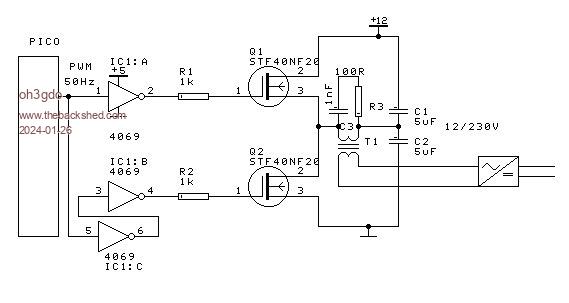
Hey Phoneicrising I remember at 1978, I did an inverter to my friend. It used thistors, and hardware oscillator, but is was about the same as my drawing. Regards Pekka |
||||
| Mixtel90 Guru Joined: 05/10/2019 Location: United KingdomPosts: 6787 |
It's possible, but you may have fun doing it. :) There are all sorts of ways you could try. Just off the top of my head... 1: Use PLAY TONE to create a 50Hz output. Apply it to a NPN transistor to get an inverted output. No put the original signal into one half of an H bridge and the inverted output into the other. You'll get AC across the H bridge. I assume you'll want to put an isolating transformer here. This method has the advantage that it's a pure sine, but the H bridhe will run hot if there's any load because it's being used in linear mode. Not all are suitable for this. 2: Use, say, 4 outputs to feed two R2R networks that are staggered so you get a 180 degree phase difference at the outputs. Feed those to the H bridge as above. No real advantage over the above, gives a rougher sine wave. If you are clever you can get this system to work very well as you can get exactly the waveform that you want. Use more bits to get better waveforms (but 8 is about the limit with standard resistors). 3: Use two PWM outputs, one using PWM SYNC to put it 180 degrees out of phase. Feed these to the H bridge. Has the advantage that it's cheap & cheerful. Has the disadvantage that any inductive load makes it inefficient - you should have a dead time between halves of the waveform. If output accuracy is important you'll need to convert a sample of the output voltage back to DC and feed it back into the Pico so it can correct the output voltage. If you can find any way to bypass the AC input and feed DC in instead then I'd strongly recommend that approach. EDIT: Another idea (depending on your load) is to use PLAY TONE to feed a normal Class D bridged power amplifier. Use that into a transformer if you want isolation. Note: If you want 8V out from a 12V supply then just turn the input signal up or down to get the voltage right. You could use the secondaries of a 12V+12V transformer and just ignore the primary (insulate the terminals as they'll be at mains voltage!). Edited 2024-01-26 05:03 by Mixtel90 Mick Zilog Inside! nascom.info for Nascom & Gemini Preliminary MMBasic docs & my PCB designs |
||||
| oh3gdo Regular Member Joined: 18/11/2021 Location: FinlandPosts: 47 |
 |
||||
| PhenixRising Guru Joined: 07/11/2023 Location: United KingdomPosts: 858 |
@oh3gdo Oh, very nice. Those particular FETs are unobtainium, however. I wish but...  Looking at the LMD18200t which handles this automagically. Was thinking PWM to waggle the "Dir" for frequency and another PWM for command output regulation. Thinking: All I need to do is feed the rectifier(s), sinewave shouldn't even matter(????) |
||||
| Mixtel90 Guru Joined: 05/10/2019 Location: United KingdomPosts: 6787 |
It needs AC for the voltage multiplier. The waveform may not be too important though. What's the current draw? An amp or so at 9V? Mick Zilog Inside! nascom.info for Nascom & Gemini Preliminary MMBasic docs & my PCB designs |
||||
| PhenixRising Guru Joined: 07/11/2023 Location: United KingdomPosts: 858 |
The existing wall-wart is rated @2.1A Voltage multiplier? I figured it would be capable of +/- 12V and I would reduce it via PWM-ing the input....maybe I got this wrong(?) Actually, the LMD18200t doesn't like a supply <12V so I can easily increase the battery voltage and chop it up with PWM....wrong track? Edited 2024-01-26 09:05 by PhenixRising |
||||
| phil99 Guru Joined: 11/02/2018 Location: AustraliaPosts: 2135 |
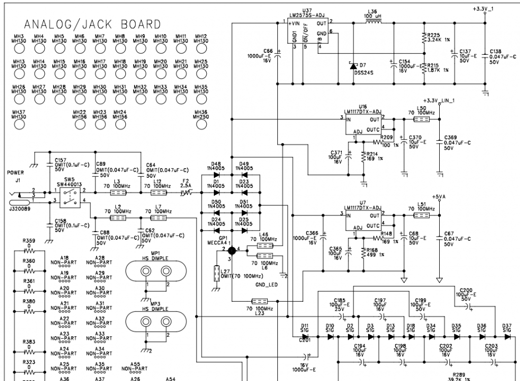
D11 to D37 string and associated capacitors are a x5 voltage multiplier. As the main bridge rectifier has a large filter cap. (C66) the RMS supply voltage is incidental, what matters is the peak voltage. 9V x √2 = 12.7V So a H-Bridge fed of a 12V battery supply will be fine, however there must not be any connection from the battery to the Analogue/Jack-board ⏚. As it's a square wave put an inductor in series with one of the output legs, or low value resistor in series with the battery to reduce inrush current to the capacitors. The value will depend on the running current, 0.5Ω to 1Ω perhaps. Headlight globes are good for this sort of thing. They have a low cold resistance yet limit the short-circuit current. Edit. PicoMite code (V5.08.00) for 50Hz complimentary outputs on pins GP0 and GP2 with 10% deadtime. setpin gp0,pwm : setpin gp2,pwm pwm 0,50,45 : pwm 1,50,45 : pwm sync 0,50 'replace above line with next line if H-Bridge requires inverted inputs. ' pwm 0,50,55 : pwm 1,50,55 : pwm sync 0,50 If your H-Bridge requires individual drive for all four legs something like this may work. setpin gp0,pwm : setpin gp1,pwm : setpin gp2,pwm :setpin gp3,pwm pwm 0,50,45,55 : pwm 1,50,45,55 : pwm sync 0,50 Edited 2024-01-26 15:34 by phil99 |
||||
| Volhout Guru Joined: 05/03/2018 Location: NetherlandsPosts: 4234 |
If I look at the over-engineered EMC filtering and ground splits, not knowing what the thing does, I would be scared feeding it with square wave, or anything that has high dV/dt or dI/dt. Volhout PicomiteVGA PETSCII ROBOTS |
||||
| Volhout Guru Joined: 05/03/2018 Location: NetherlandsPosts: 4234 |
If I look at the over-engineered EMC filtering and ground splits, not knowing what the thing does, I would be scared feeding it with square wave, or anything that has high dV/dt or dI/dt. And without transformer, as you indicate Phill) there is a risk of battery - getting in contact with GND. Volhout Edited 2024-01-26 22:06 by Volhout PicomiteVGA PETSCII ROBOTS |
||||
| Mixtel90 Guru Joined: 05/10/2019 Location: United KingdomPosts: 6787 |
I would definitely try a class D audio amp feeding a 12V transformer secondary with the output taken from the other 12V secondary. Feed that lot from PLAY TONE set to 50Hz and you should be fine. The transformer can be small - 30VA should be fine. Use a normal EI type, not a toroidal type. The amp can be around 30W output, probably. You'll get a decent sine wave. You may need to add a heatsink to the amp. Not all are provided with a large enough one. Mick Zilog Inside! nascom.info for Nascom & Gemini Preliminary MMBasic docs & my PCB designs |
||||
| PhenixRising Guru Joined: 07/11/2023 Location: United KingdomPosts: 858 |
This is such a cool idea....I just have to try this  |
||||
| PhenixRising Guru Joined: 07/11/2023 Location: United KingdomPosts: 858 |
@Mixtel90 I am flexible regarding the DC source so could I get away with no xfmr? |
||||
| Mixtel90 Guru Joined: 05/10/2019 Location: United KingdomPosts: 6787 |
That's something I've not tried. You'd have to make sure that neither side of the battery could ever get connected to the equipment ground - or you'd probably lose an output mosfet in a puff of magic smoke. If that can be done then I think it might work. The Pico would have to be on the battery and amplifier common (it's not ground, that's what the load is connected to) in order to drive the amp. I'd do initial tests with a couple of ohms in series with the amp output. There are some pretty big caps in there. Bring up the amp supply gently - it might be very unstable with that load. Mick Zilog Inside! nascom.info for Nascom & Gemini Preliminary MMBasic docs & my PCB designs |
||||