|

|
Forum Index : Microcontroller and PC projects : Cheap and easy 6-button controller
| Author | Message | ||||
| Mixtel90 Guru Joined: 05/10/2019 Location: United KingdomPosts: 6798 |
I've been playing with the idea of just having GP26, GP27, G28 and RUN on an expansion port, together with GND and 3V3. You could use it for: A combination of analogue and digital inputs up to 3 An I2C (I2C2) port with an interrupt line and reset SPI2 (but no extra signals so very limited) Then I came up with this (repeat for each ADC input): 3V3 ! 3V3 1K ! ! 1K BUTTON 1 ! ! +------- 10K -----+------- OUT ! ! 1K BUTTON 2 ! ! GND GND You only need the potential divider resistors once, the 10K resistors isolate the 3 channels. The 1K resistor above button 1 prevents a power supply short! Normally the output will sit at half supply, so button1 = (PIN(n)>2) button 2 = (PIN(n)<1) Yes, you could do this with a single resistor string but it's slower to read and needs selected resistor values. It can't handle simultaneous presses either, this can handle 3 if they are on different channels. Nothing in this design is critical. You could put a cap from the mid voltage point to GND, but I doubt if it's needed. Mick Zilog Inside! nascom.info for Nascom & Gemini Preliminary MMBasic docs & my PCB designs |
||||
| stanleyella Guru Joined: 25/06/2022 Location: United KingdomPosts: 2129 |
GP26, GP27, G28 and RUN? is that 4 pins or 3? I like 2 buttons detected, my a-d arduino 5 button is just each button. You got to think how many buttons you need, like I'm making 8 button board but with i2c expander ..when I get pull ups to work but when would I need 8 buttons? it's got 16 channels so use 8 for in and 8 for out as a versatile board needing only 2 gpio for i2c. |
||||
| Volhout Guru Joined: 05/03/2018 Location: NetherlandsPosts: 4243 |
Hi Mick, GP26..28 are ADC channels Its is easy to connect multiple switches to 1 ADC pin, and if you use R-2R-4R-8R resistors you can even detect double presses. Volhout PicomiteVGA PETSCII ROBOTS |
||||
| stanleyella Guru Joined: 25/06/2022 Location: United KingdomPosts: 2129 |
Can you post a circuit with common value resistors please for 6 buttons please. |
||||
| Mixtel90 Guru Joined: 05/10/2019 Location: United KingdomPosts: 6798 |
Stan: If you are using a I2C expander (using GP26 and GP27) it's useful to have the Reset line to clear it to defaults, hence the RUN signal. You can also use GP28 as the interrupt to signal that a pin has changed. This approach is good if you want 8 or 16 digital inputs. You could also connect to another Pico using this approach. As I said, I know you can put multiple buttons on one input. However, for 6 buttons you need: R 2R 4R 8R 16R 32R that's quite a big range and doesn't fit into E24 series single resistors. This is very fast to read and has a very high noise immunity. There are no cumulative errors. Mick Zilog Inside! nascom.info for Nascom & Gemini Preliminary MMBasic docs & my PCB designs |
||||
| Volhout Guru Joined: 05/03/2018 Location: NetherlandsPosts: 4243 |
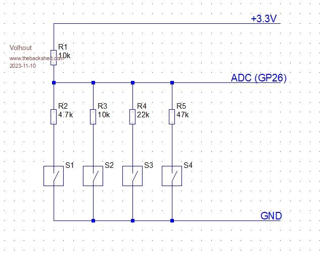
I think it is do-able to decode 4 keys with one ADC input. With following circuit.  This will give you 80mV minimum resolution for 2 key press detect (change R1 to 4.7k). This is in the "2-button" column in the red fields (0.080 = 0.080 volt = 80 milivolt) Result from following analysis: And a small (not tested) MMBasic program to show how it works. You scan through the voltage levels in the array, and see where the ADC pin voltage crosses a threshold. 'key decode for ADC connected keys dim v(11)=(3.142,2.860,2.616,2.379,2.173,2.031,1.805,1.611,1.531,1.413,0.668,0) dim k$(11)length 5=("no","S4","S3","S3+S4","S2"."S2+S4","S2+S3","S1","S1+S4","S1+S3","S1+S2","fault") setpin gp26,adc do volt=pin(GP26) i=12 do i=i-1 loop while volt < v(i) print k$(i) pause 100 loop You can extend this of coarse to 5 or 6 swiches, but you may have to calibrate the ADC, and add averaging and noise filtering. Since (as you can see in the analysis) there will be very small steps you need to detect. The ADC resolution (4096 steps for 3.3V) has a 1mV resolution, so technically 6 buttons is possible. You may need precision resistors in non E96 values to get sufficient accuracy. Edited 2023-11-10 18:42 by Volhout PicomiteVGA PETSCII ROBOTS |
||||
| stanleyella Guru Joined: 25/06/2022 Location: United KingdomPosts: 2129 |
Thanks Mick and Volhout. |
||||