|

|
Forum Index : Microcontroller and PC projects : HC-12 Spring Antenna Orientation
| Author | Message | ||||
| Andrew_G Guru Joined: 18/10/2016 Location: AustraliaPosts: 847 |
Hi all, I'm trying to fit an HC-12, with a spring antenna, into a small space so that the spring is not vulnerable. It would be safest if I could align the spring along the edge of the PCB. This puts it at 90deg to most of my network (about a dozen all chirping away). How critical is it that the springs are aligned and can some be pointing 'down' vs 'up'? The unit will be relatively close to the base station (say 20m) with say one brick wall. It won't be 'mission critical' data. Many thanks, Andrew (PS: I'm not in a position to do much testing - we have been living in a hotel for 16 months with only limited gear.) |
||||
| Plasmamac Guru Joined: 31/01/2019 Location: GermanyPosts: 554 |
My tests shows the best results if booth have the same alignment. It can penetrate 2 walls and 20 m distance. In LoS it works 300m Plasma |
||||
| Andrew_G Guru Joined: 18/10/2016 Location: AustraliaPosts: 847 |
Hi Plasma, Thanks. Any guess as to how bad it might be at 90deg (eg 50%?? of an aligned pair)? Cheers, Andrew |
||||
| Mixtel90 Guru Joined: 05/10/2019 Location: United KingdomPosts: 6798 |
The little spring antenna is remarkably inefficient no matter how you align it. Regardless of the input power, the erp (effective radiated power) isn't great when using that. The key point is to regard the furthest end from the HC-12 as the RF "hot" end and keep it away from all metalwork, including the PCB ground plane and case. Very best results will normally be with it pointing straight up vertically, away from the PCB and the ground, in which case the surface of the HC-12 and any PCB underneath it will act as a RF ground plane to equalize the radiation pattern a bit (it will normally try to radiate upwards in a steep donut shape). If you have to run the antenna parallel with the PCB then remove any ground plane on both sides of the board along its length, particularly at the "hot" end. If you use an external antenna then be very careful to stay within the regulations for your country. It is very easy to radiate too much power. In the UK, in particular, it is the erp that is measured so the type and positioning of any antenna is critical. Mick Zilog Inside! nascom.info for Nascom & Gemini Preliminary MMBasic docs & my PCB designs |
||||
| Andrew_G Guru Joined: 18/10/2016 Location: AustraliaPosts: 847 |
Thanks Mick (not the Big one), You might guess the pair of PCBs I'm trying to fit it within. Cheers, Andrew |
||||
Grogster Admin Group Joined: 31/12/2012 Location: New ZealandPosts: 9308 |
I've used literally hundreds of HC12's now, and they are a fantastic little module.  Most of my designs use the helical antennas, and despite their inefficiencies as Mick points out, they still work rather well, and are definitely the best choice if you need to keep things as small as possible. I have used helicals both sticking straight up from the antenna hole, and also laying flat in the same horizontal plane as the HC12 module itself. I've never had any issues using them either way, with the key thing to note is what Mick said: Those are indeed the most important things to note. If you have ANYTHING metallic even close to the hot-end of the helical, it will directly affect the performance. Helicals are particularly sensitive to that as Mick says, so that must be avoided if at all possible. Sometimes, the design simply does not allow for that, but TRY to make that your #1 rule for helical antennas.  If your data is not mission-critical as you say, you could have your nodes retransmit. With only 20m or so and a brick wall, I would not really expect any issues no matter what orentation of the helical antennas. True - you might not get the maximum range if not aligned, but for only 20m, I think just about anything should work. If you want or NEED maximum range for a given output power, it becomes much more important to have your antennas in the same vertical or horizontal plane, out in the open and away from anything metal, but for very short range, you can just about get away with a bit of wet string.  I could go into more rants about antennas and roof antennas etc, but I don't think you are using that sort of arrangement - just helical to helical, correct? Smoke makes things work. When the smoke gets out, it stops! |
||||
| Andrew_G Guru Joined: 18/10/2016 Location: AustraliaPosts: 847 |
Thanks Grogs (and Mick and Plasma). That all makes sense. (Good luck with CMM2 sales). Cheers, Andrew |
||||
Grogster Admin Group Joined: 31/12/2012 Location: New ZealandPosts: 9308 |
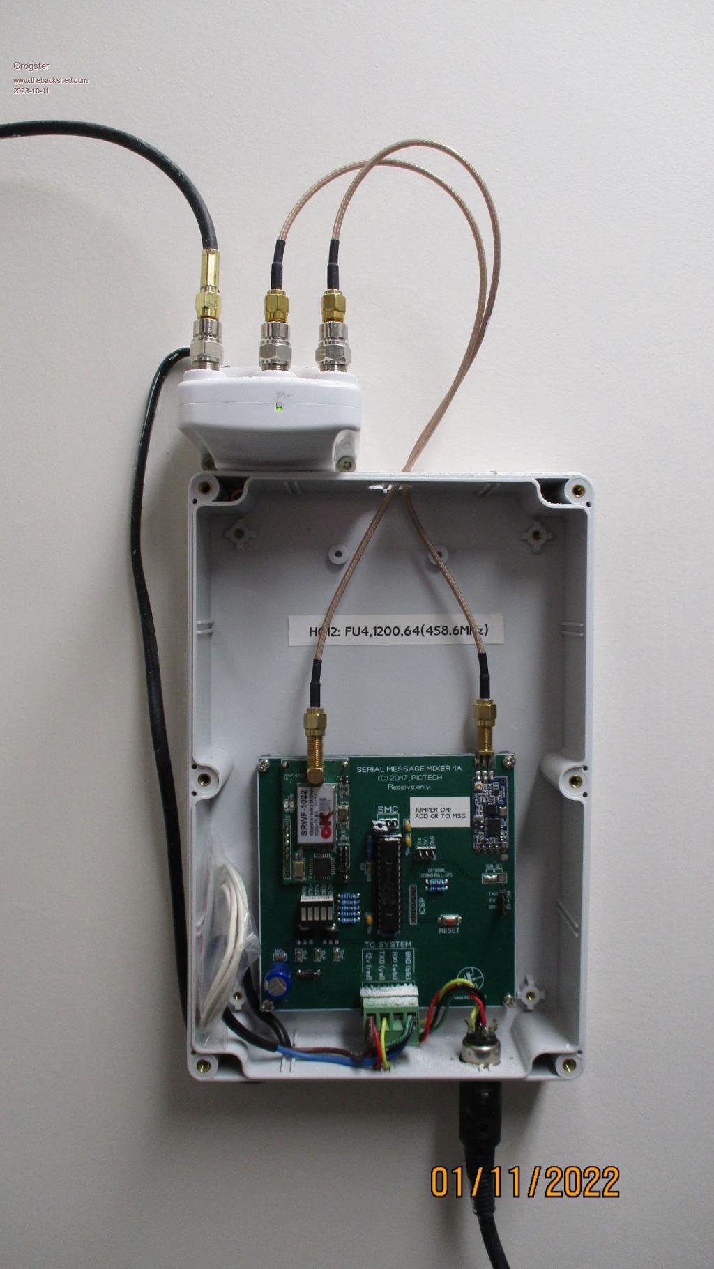
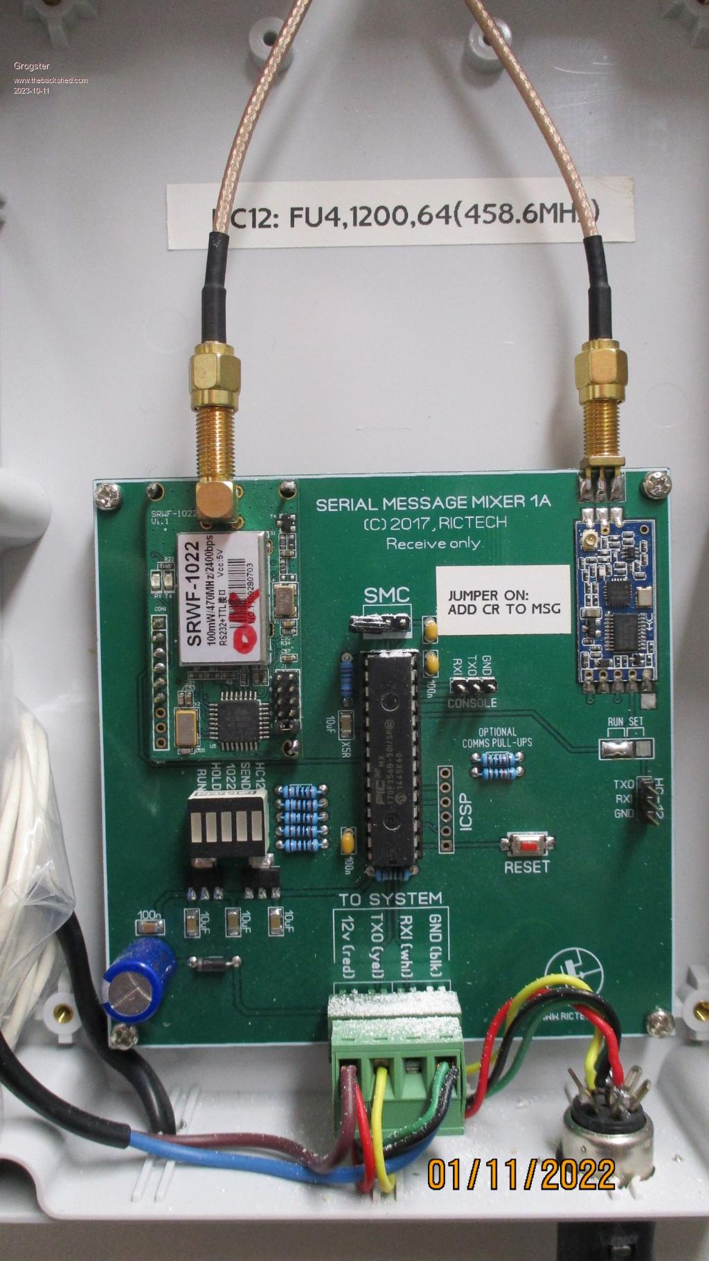
Re: CMM2 sales - yes, I only got five boards made at this stage. I did not want to stock up on heaps of them, if I can't move them.  As an example of HC12's connected to a roof antenna, look at these photos:   In this arrangement, we have TWO different RF networks, both wanting to talk to the base station. One network consists of SunrayRF SW1022 RF modules, and the other consists of HC12 modules. This unit listens to both networks, translates the messages, and sends them out to the base station for processing. With respect to the HC12's, I have the HC12 module connected to an SMA socket, which is then connected via coax to the output of a TV booster amp(Kingray SA122 from memory), with the input being connected to the base-loaded whip antenna up on the roof. This arrangement works EXTREMELY well, and I can easily get several kilometers of range from the HC12's when running at 100mW output. Here in NZ, we very conveniently have a slice of UHF band at 458.6MHz, whic is unrestricted on use and power up to 500mW, so I plopped my HC12 network there, and can run full power to maximize the range, all perfectly legally.  As Mick mentions though, you need to check with YOUR countries regulations, but even with limited output power, this roof antenna arrangement + amp + message mixer should still work very well indeed. Roof-mounted antennas are still the best.  Edited 2023-10-11 15:23 by Grogster Smoke makes things work. When the smoke gets out, it stops! |
||||
| Andrew_G Guru Joined: 18/10/2016 Location: AustraliaPosts: 847 |
Wow - that makes my little 6" external antenna on my weather station look a little tame. Cheers, Andrew |
||||
| JohnS Guru Joined: 18/11/2011 Location: United KingdomPosts: 3802 |
I love the light dusting of ... snow? icing sugar? John |
||||
| Mixtel90 Guru Joined: 05/10/2019 Location: United KingdomPosts: 6798 |
Strictly speaking the "springy thingy" supplied with the HC-12 isn't a helical antenna at all. The dimensions are wrong. A true helical radiates circular polarized waves and is directional. The "springy thingy" is actually a "vertical whip" antenna that has been made into a spring. I doubt very much if the length of wire used is optimal and it certainly won't ne by the time it's been wound. A vertical whip has a high angle of radiation unless it has a ground plane. Usually the ground plane needs to be in the shape of a cone at these frequencies if you want a horizontal radiation pattern. A true 1/4 wave vertical for 433.5MHz should be 16.4cm long. There should be four to six ground plane "radial" wires sloping down from its base at 45 degrees, each 18.4cm long. As you can see, this isn't going to be PCB mounting. :) The 433MHz band is actually allocated to radio amateur and MOD usage in the UK. The HC-12 isn't a good device to use here, no matter how you use it. You should certainly turn the power right down and stick with the "springy thingy" because if you try to get full range you may get a knock on the door from Ofcom and/or the MOD. Mick Zilog Inside! nascom.info for Nascom & Gemini Preliminary MMBasic docs & my PCB designs |
||||
Grogster Admin Group Joined: 31/12/2012 Location: New ZealandPosts: 9308 |
Gib-board(Drywall) dust when they drilled new holes for the cables to run through. Smoke makes things work. When the smoke gets out, it stops! |
||||
| Mixtel90 Guru Joined: 05/10/2019 Location: United KingdomPosts: 6798 |
t adds an almost seasonal touch, with the LED fairy lights. Glad you didn't include tinsel though, that would have been a bit early. :) Mick Zilog Inside! nascom.info for Nascom & Gemini Preliminary MMBasic docs & my PCB designs |
||||
| JohnS Guru Joined: 18/11/2011 Location: United KingdomPosts: 3802 |
That's so disappointingly ordinary! (I've heard of that stuff, just not got any. Welcome to masonry bits and pesky embedded flints.) John Edited 2023-10-14 19:45 by JohnS |
||||
| Mixtel90 Guru Joined: 05/10/2019 Location: United KingdomPosts: 6798 |
Not to mention trying to get any sort of a drill through the wall of a stone-built house. :( Mick Zilog Inside! nascom.info for Nascom & Gemini Preliminary MMBasic docs & my PCB designs |
||||
| JohnS Guru Joined: 18/11/2011 Location: United KingdomPosts: 3802 |
Or wifi / mobile phone signal... John |
||||