|

|
Forum Index : Microcontroller and PC projects : Armmite F4 Ribbon cable extension between Display and Board
| Author | Message | ||||
| Glen0 Regular Member Joined: 12/10/2014 Location: New ZealandPosts: 86 |
I want to separate the display from the board so that I can mount the display and board in different places. I was thinking of using ribbon cable to achieve this. I could terminate the board-end of the ribbon cable with a 32 Way IDC Line socket, but what is readily available to terminate the other end of the ribbon cable, that would connect to the Display side.  |
||||
bigmik Guru Joined: 20/06/2011 Location: AustraliaPosts: 2914 |
Hi GlenO, You can get both Male and Female crimp (IDC) headers although they do not seem to be available in 32 pin variants. There are many 34 pin types though. As neither the F4 board and the display seem to have a location knob you could make a cable of suitable length out of the 34 way types and block the last pair of pins so you can't offset the plug accidentally. Sample types I found on Element14 are Male IDC and Female IDC The male in the link above is relatively expensive but e14 also List another but the image shows a 16way whilst the description states 34 way. But I know and have used male and female IDC headers before so they are available. A search through Aliexpress may come up with some cheaper varieties for you. Kind Regards, Mick EDIT ** I did a quick check on Aliexpress and indeed they do stock male and female just search for IDC male (or female) and select the ones you want. But I also found these 10cm (4") cables pre-made with 1 male and 1 female already fitted for about $5AU ($3US) posted. Note this link is transient so you may have to do some searching for them if the link disappears.10cm Extension Mik . Edited 2023-08-16 14:49 by bigmik Mick's uMite Stuff can be found >>> HERE (Kindly hosted by Dontronics) <<< |
||||
| OA47 Guru Joined: 11/04/2012 Location: AustraliaPosts: 926 |
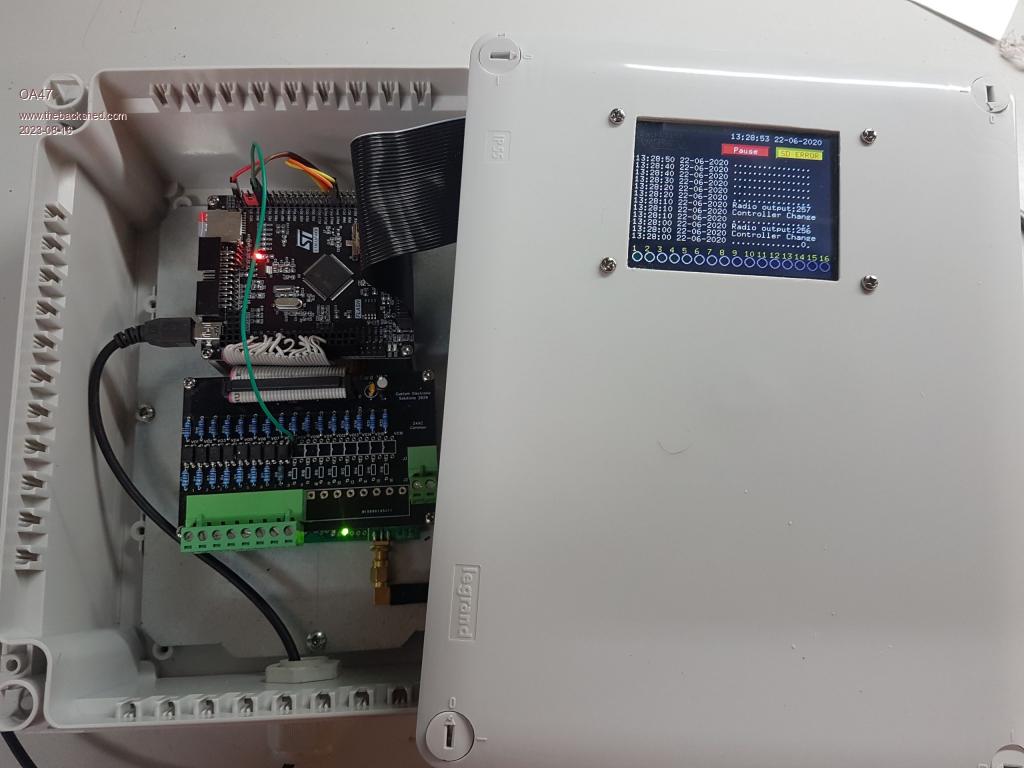
Glen, I have done this before and you cannot use IDC connectors both ends as unlike say a floppy drive or hard drive the pins are reversed on on connector to the other. The only successful way I have been able to accomplish an extension cable is to use an IDC one end and individually solder a header strip to the other end. I will try and find a photo and post it. Hopefully this helps. 0A47 |
||||
| OA47 Guru Joined: 11/04/2012 Location: AustraliaPosts: 926 |
Sorry this photo isn't that clear and only shows the IDC end of the black ribbon cable but it does show that it can be done.  0A47 Edited 2023-08-16 15:15 by OA47 |
||||
bigmik Guru Joined: 20/06/2011 Location: AustraliaPosts: 2914 |
Hi 0a47, You should be able to use the male and female IDC connectors with correct orientation. as it is effectively an extension cable. The problem as you described is if you had two female connectors (simply adding pins into one will not work as it will swap all the odd with even pins around and vice versa). I have used the female/male IDC on cables as extension with no issues. Of course some manufactures `DID' swap odds and evens to force you to buy their cables (Exatron stringy floppy - from the 70's -- comes to mind) but I doubt you could find one these days, using standard male and female IDC headers will be perfectly OK. Of course buzz it out before plugging it in. Regards, Mick Edited 2023-08-16 15:38 by bigmik Mick's uMite Stuff can be found >>> HERE (Kindly hosted by Dontronics) <<< |
||||
| OA47 Guru Joined: 11/04/2012 Location: AustraliaPosts: 926 |
Gday Mick, I may have gone the long way round in producing my extension cable as I was not aware that you could get male IDC that would give you the crossover effect to make an extension cable, in fact with my years of exposure to PCs and computer equipment I dont recall seeing anything like it. With the PC100 variants of boards and cards in the day, this type of extension cable would have been glorious. Thankyou for your knowledge. 0A47 |
||||
| Mixtel90 Guru Joined: 05/10/2019 Location: United KingdomPosts: 6798 |
You can get long male header pins in 1-row and 2-row (sometimes used for stacking PCBs). How about a length of that to convert the female header to male, then use a female-female lead? Mick Zilog Inside! nascom.info for Nascom & Gemini Preliminary MMBasic docs & my PCB designs |
||||
bigmik Guru Joined: 20/06/2011 Location: AustraliaPosts: 2914 |
Hi Mick, All, @Mick As I mentioned before, simply plugging male pins into a female header will not do what you need as the odd and even numbered pins will be swapped, @Oa47 There is No crossover of pins using a `normal' male and female IDC crimp (Unless you were able to find a weird non standard connector which I doubt exists these days) as pin 1 of the male will go to pin 1 of the female connector. IF you simply plugged pins into a female header it will not have pin 1 (or any other) in the correct position. I have used the male/female cables numerous times to extend cables so boards could be worked on outside of the case, if they didn't work the boards would never have worked as expected. Regards, Mick Mick's uMite Stuff can be found >>> HERE (Kindly hosted by Dontronics) <<< |
||||
| Mixtel90 Guru Joined: 05/10/2019 Location: United KingdomPosts: 6798 |
I'm going to have to think this one out, Mick. :) Isn't that why FDC ribbon cables have their connectors on opposite sides of the ribbon? It won't work if both connectors are on the same side. EDIT After further thought. It needs a special ribbon with one female IDC connector on each side so that they face away from each other. Pin 1 is then on the same corner of both connectors. The bottom connector goes to the F4, the top one has a male-male header strip to convert it to male so that the display can be plugged onto it. The F4 and display have the same relative rotation as normal, so the display is actually pushed over to the side by the length of the ribbon. You can't use a normal ribbon with connectors on the same side because, as Big Mick says, the odd and even rows get reversed. . Edited 2023-08-16 17:58 by Mixtel90 Mick Zilog Inside! nascom.info for Nascom & Gemini Preliminary MMBasic docs & my PCB designs |
||||
| RendPhys Newbie Joined: 29/10/2020 Location: NetherlandsPosts: 6 |
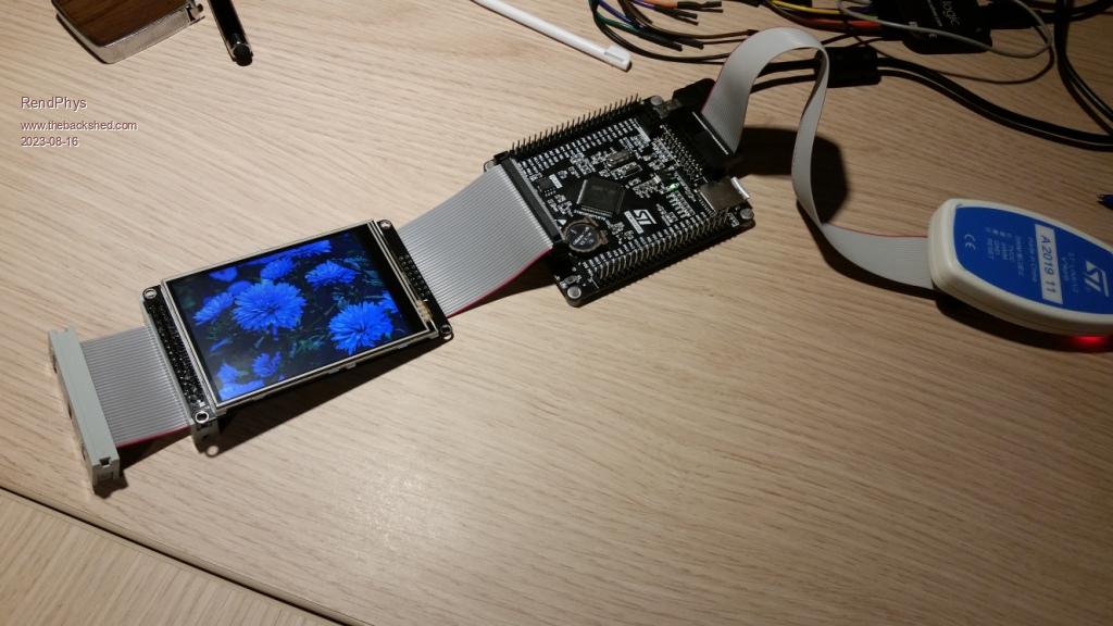
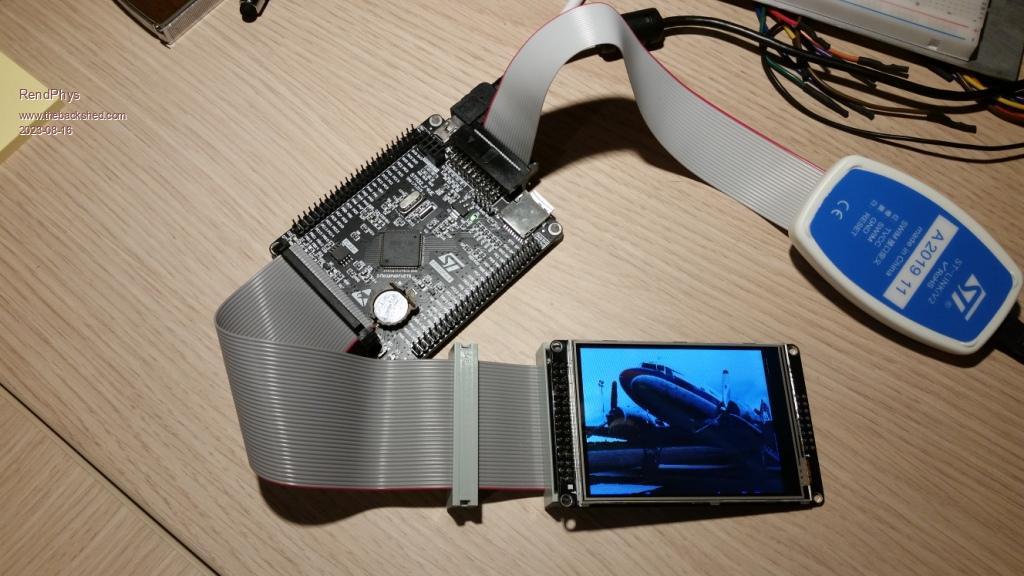
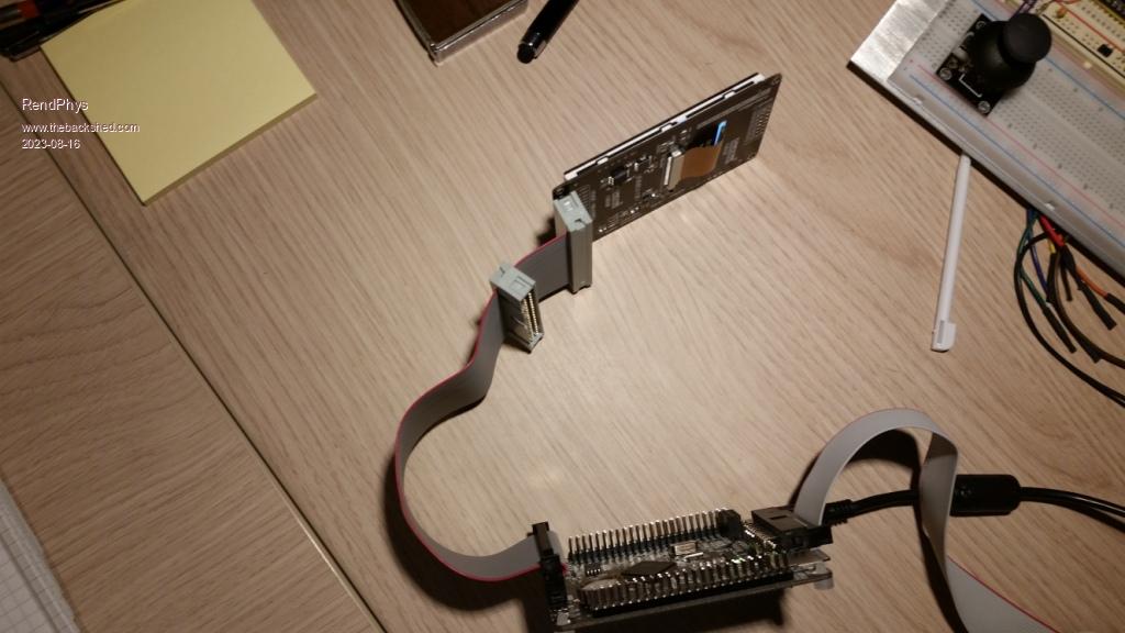
Hi all, I do indeed use the IDC cables and connectors to position the LCD on any wanted position. As far as I know there are no 32-pins standard cables, so I use the 34-pins variant. Be aware of the proper positioning of the (unused) pins, so indeed the proper pins are connected. Can be easily verified using an ohm-meter, of course. Some links to start searching: https://www.aliexpress.com/item/4001244049708.html? https://www.aliexpress.com/item/33029492417.html? Here some pictures of how it can be done... Best regards, Henk. |
||||
| RendPhys Newbie Joined: 29/10/2020 Location: NetherlandsPosts: 6 |
   |
||||
bigmik Guru Joined: 20/06/2011 Location: AustraliaPosts: 2914 |
Hi All, As RendPhys, shows they do work as I said. @Mick, Have a good look at the crimp IDC female connector before you crimp it, each pin has a Vee shape cutter that cuts into each wire in the cable, it does not matter what side of the cable you crimp it onto pin one of the connector will always go to the same wire in the cable. The reason, I presume, that some cables are crimped on alternate sides and others on the same side is purely for convenience of plugging into your devices, this will vary depending on physical layout but there is no electrical difference which side of the cable it is crimped to. If you have a spare connector .. try it.. I had 30 plus years of using these type of cables and I am certain they work as I stated. Regards, Mick Mick's uMite Stuff can be found >>> HERE (Kindly hosted by Dontronics) <<< |
||||
bigmik Guru Joined: 20/06/2011 Location: AustraliaPosts: 2914 |
Oops Duplicate post deleted, Sorry about that Mick Edited 2023-08-16 22:13 by bigmik Mick's uMite Stuff can be found >>> HERE (Kindly hosted by Dontronics) <<< |
||||
| Mixtel90 Guru Joined: 05/10/2019 Location: United KingdomPosts: 6798 |
You know, BM? You're right. :) Thanks. Mick Zilog Inside! nascom.info for Nascom & Gemini Preliminary MMBasic docs & my PCB designs |
||||
| Glen0 Regular Member Joined: 12/10/2014 Location: New ZealandPosts: 86 |
Thanks everyone. Armed with all of the advice and cautions I will tackle this soonish. I will post any successful outcomes. Much appreciated as always. |
||||