|

|
Forum Index : Microcontroller and PC projects : Fun and games with the JDY-40
| Author | Message | ||||
| Mixtel90 Guru Joined: 05/10/2019 Location: United KingdomPosts: 6798 |
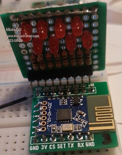
These things are fun, not to mention stupidly cheap from AE. :)  I just fed the 8 GPIO pins of a JDY-40 to 8 GP pins of a RP2040-Zero and set the system up so that the PicoMite counts up on the PORT. The JDY-40 sends the data to another one connected to LEDs. With the transmit power set as low as it will go and the baud rate set to 19200 (the maximum) it's just losing signal with the transmitter at the front of the house and the receiver at the bottom of the back yard if I put it close to the wall. Easily enough power to cover a room or two in many cases. I'll re-test the range with text data later. The manual is reasonably good but doesn't make some things clear at all:- First, the frequency. The 2.4GHz band goes upwards from 2.4GHz to 2.4835 GHz and is split into 14 channels. Thes overlap a lot, so if you want no overlap you can only use three or four channels in any given area (approx. 8m diameter). The manual says there are 128 channels, which would put the thing way out of band if it's true. According to the data sheet for the chip, the register RF_CH sets the channel number. The frequency is then 2400 + RF_CH MHz. Any value over 82 will be out of band. Legal channels will, in theory, be numbers 12, 17, 22, 27, 32, 37, 42, 47, 52, 57, 62, 67, 72 and 84 (the latter not available in the US). Note that as the chip is a microcontroller it may be scaling the channel numbers in some unspecified way, but this is as close as I can get. The output current from the GPIO pins is 3mA maximum as far as I can tell. I don't know how, but the manual specifies more steps of transmit power level than are available. :) Mick Zilog Inside! nascom.info for Nascom & Gemini Preliminary MMBasic docs & my PCB designs |
||||
Grogster Admin Group Joined: 31/12/2012 Location: New ZealandPosts: 9308 |
Doesn't look like there is much in the way of output RF filtering. I wonder what they look like on a spectrum analyser?  Do you happen to have a link you could share? Smoke makes things work. When the smoke gets out, it stops! |
||||
| Mixtel90 Guru Joined: 05/10/2019 Location: United KingdomPosts: 6798 |
No circuit anywhere. :( The only info I've found is: English user manual BK2461 data sheet I wouldn't expect any more filtering than you'd get in a 2.4GHz wireless keyboard or mouse. They'll look vile, but the fundamental won't be too big, never mind the sproggies... :) EDIT: Interesting problem while testing text transfer. This setup works great: Receiver unit connected to PC via TTL-USB converter and YAT software. Transmitter has a YD-2040 sending the text and is powered from USB-C from the PC. If the transmitter is swapped over to run from a power bank the data is *far* slower and chopped up. Not running well at all. If I then quickly swap the lead from the power bank to the PC it remains like this. However, switch the transmitter off and on again (using AUTORUN here) and all is well again. It's almost as if it wants the USB keep-alive to keep the COM port running properly (that may be way too fanciful at this stage). I'll rearrange it later to use a RP2040-Zero for the transmitter. Edited 2023-06-29 17:26 by Mixtel90 Mick Zilog Inside! nascom.info for Nascom & Gemini Preliminary MMBasic docs & my PCB designs |
||||
| scruss Regular Member Joined: 20/09/2021 Location: CanadaPosts: 86 |
Ah, the good old NRF24L01. A serial cable without the cable, pretty much. |
||||
| Mixtel90 Guru Joined: 05/10/2019 Location: United KingdomPosts: 6798 |
This is even simpler than the NRF24L01. I never managed to get a pair of those to do anything. :) Mick Zilog Inside! nascom.info for Nascom & Gemini Preliminary MMBasic docs & my PCB designs |
||||