|

|
Forum Index : Microcontroller and PC projects : PM: Logging VESA Terminal...
| Author | Message | ||||
Grogster Admin Group Joined: 31/12/2012 Location: New ZealandPosts: 9308 |
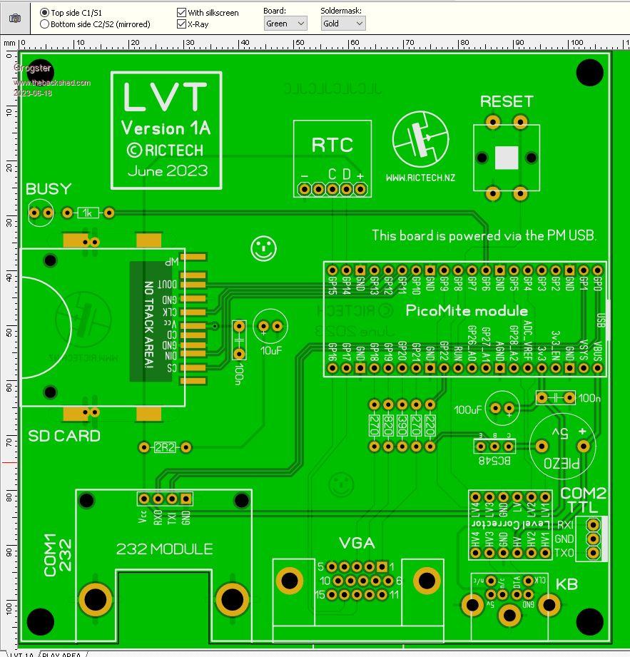
I needed something simple for logging serial data, and decided something that would use the monitor's standard VESA mounting holes could be useful. In my case, it uses the 100mm VESA standard.  Its primary use, is logging anything received on COM1(RS232), to an SD card file, but I have also routed out COM2, which is 5v tolerant via the level-corrector. Nothing fancy, but it mounts neatly on the back of any monitor with 100mm VESA mounting holes, and is powered by the USB cable, as many monitors now have a USB port, so it becomes very neat and self-contained. If anyone is interested, let me know, and I can compile and upload a constructors pack in the form of a ZIP file. Smoke makes things work. When the smoke gets out, it stops! |
||||
| Mixtel90 Guru Joined: 05/10/2019 Location: United KingdomPosts: 6798 |
That's neat. :) Might be an idea to add 100nF across the reset button and, possibly, a 10k pullup. Just thinking, it's hardly a noise-free location. Personally, I'd increase the base resistor of the BC548 to about 1k or even 2K2. hFE is going to be over 100 so that's fine. The transistor can only handle 100mA anyway. There's no point in loading the PicoMite output unnecessarily. I had to replace my montor some time ago and I grabbed an AOC off ebay as a replacement. You know what? I think I may have the only LCD display without any VESA fixing holes whatsoever on the planet. In fact, there are no rear fixing holes anywhere, for anything, not even to hold the case together. Edited 2023-06-18 16:54 by Mixtel90 Mick Zilog Inside! nascom.info for Nascom & Gemini Preliminary MMBasic docs & my PCB designs |
||||
Grogster Admin Group Joined: 31/12/2012 Location: New ZealandPosts: 9308 |
Damn....  I just noticed the silkscreen is wrong. 548 base resistor is indeed 2k2, but I have it listed there as 220 - silkscreen typo. The 5v piezo is just there to "Beep" on receipt of a message, to draw your attention to the screen, but I am not even sure if I will even use it - but better to have it and not need it, then to need it and not have it.  Could add the 100n/10k to the reset button, but so far, noise from the monitor has not proven to be a problem - yet.  Smoke makes things work. When the smoke gets out, it stops! |
||||
Quazee137 Guru Joined: 07/08/2016 Location: United StatesPosts: 571 |
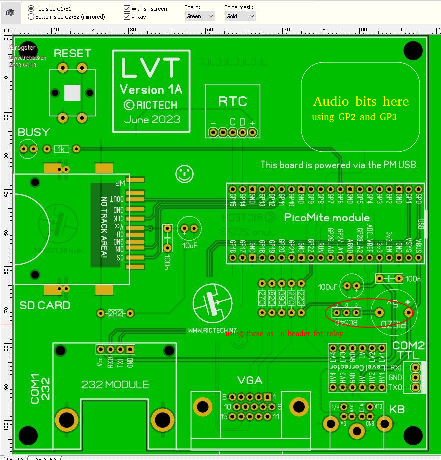
Just a thought a few of my thin line LCD VGA monitors have speakers that you could play flac files from the SD card giving more information on any alert. I could give vocal setup and calibration instructions to operators make things very cool more what todays technicians kind of expect from us. The Picomite has it built in just need the very basic hardware to make use of it. Or a sea of holes with header of unused pins from the Picomite. Even pull diagrams from SD to go with vocal instruction. DAM this is WOW I like the idea of this being a front end to a group of Picomite controllers. RS232 very good range and the controllers can daisy the RS232. One other thought add a relay that could be activated. For my use power down all pumps and fire the tower alert beacons. Best is MMBasic is there on this and my controllers. We have the WEBmite viva wifi but some places an ether port is better with most newer water towers wiring already have ability to connect to LAN. Quazee137 VERY BIG THANKS !!!! GREAT IDEA better than tablet and USB I was thinking about trying. Edited 2023-06-19 15:37 by Quazee137 |
||||
Grogster Admin Group Joined: 31/12/2012 Location: New ZealandPosts: 9308 |
I've always liked the VESA mounting standard on the back of MOST monitors, cos I use mostly Intel NUC PC's these days, and they are designed to use that mount. So, I thought: "Why not make a PM PCB to use that VESA mount!" I could add the inductor-based LPF for the audio to the PCB, if you thought that would be worthwhile. In my application, I did not need sound and never would, other then the piezo beeper, but I CAN see where coupling into the monitor's audio-in jack could be a good thing.  Smoke makes things work. When the smoke gets out, it stops! |
||||
Quazee137 Guru Joined: 07/08/2016 Location: United StatesPosts: 571 |
Hope it ok here is a markup of your board. A picture in place of paragraph.   Quazee137 Edited 2023-06-19 17:23 by Quazee137 |
||||
| Andrew_G Guru Joined: 18/10/2016 Location: AustraliaPosts: 847 |
Hi Grogs, I know you don't want a design by committee but one of my pet gripes is that the USB connector has to project beyond the PCB's footprint. For example, on your PCB, if the Pico were moved a little to the left one could have the USB completely within the PCB - resulting in a smaller enclosure. A small hole (with a grommet?) vs a big one without. Just my AU$0.02's worth. Cheers, Andrew |
||||
| Mixtel90 Guru Joined: 05/10/2019 Location: United KingdomPosts: 6798 |
Why not just use a flying USB-A lead for power and not use the Pico socket at all, Andrew? I don't know of any TVs where the USB is anything but USB-A and you get the joy of having to find somewhere to lose 500mm of USB lead behind the telly - just like everybody else's boxes. ;) I know *exactly* what you mean about VESA fixings, Grogster. I too use little fanless PCs and it's annoying not having anywhere to mount one. Mind you, I did fasten a 7-port powered USB3 hub onto the monitor support with tie-wraps. :) Mick Zilog Inside! nascom.info for Nascom & Gemini Preliminary MMBasic docs & my PCB designs |
||||
Grogster Admin Group Joined: 31/12/2012 Location: New ZealandPosts: 9308 |
@ Quazee137 - OK, gimmie a couple of days and I will update here. @ Andrew_G - I know what you mean, but in this case, the PCB is supposed to just mount on the VESA holes. No case or enclosure at all, the PCB just hangs on the back of the monitor - job done.  @ Mick - Yes exactly. The board is designed to be run from a USB-A to micro-USB lead, and is powered by the monitor's USB socket, making it all pretty self-contained. For those monitors WITHOUT a USB socket, then an external plug-pack adaptor thing will be needed, but they are a dime a dozen these days too. Smoke makes things work. When the smoke gets out, it stops! |
||||
Quazee137 Guru Joined: 07/08/2016 Location: United StatesPosts: 571 |
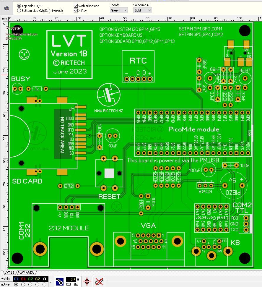
Silkscreen the options some where.  Thanks I'll be getting a few to go with the monitors my son is dropping off.  Quazee137  |
||||
| phil99 Guru Joined: 11/02/2018 Location: AustraliaPosts: 2137 |
I opened up the monitor, found the 5V supply and wired the USB lead power wires to it. Fed out through a ventilation slot. |
||||
Grogster Admin Group Joined: 31/12/2012 Location: New ZealandPosts: 9308 |
Nice idea, Phil, if you are prepared to do that!  Smoke makes things work. When the smoke gets out, it stops! |
||||
Grogster Admin Group Joined: 31/12/2012 Location: New ZealandPosts: 9308 |
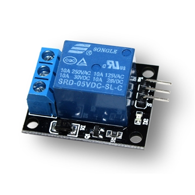
@ Quazee137 - how does this suit?  - RESET button moved, and now has 10k pull-up and 100n decoupling to satisfy Mick.  - Standard audio LPF added. - SMD 3.5mm stereo socket added. - OPTION's and SETPIN's for this board added to silkscreen. Happy? Not bothered with the relay header, as you can simply NOT install the 5v piezo, and put PCB-pins in its place, and then wire an external relay to those pins. You will need to put a back-EMF diode across the external relay coil though, or the 548 transistor will self-destruct. Also, be aware that the 548 is only rated for 100mA. That was fine for driving a wee piezo beeper, but if you planned to drive a relay, I would swap that for a BC337 which can handle much more current, but has the same CBE pinout. I can link the thread to the SD card socket and the SMD stereo socket if you like, but they are very common(and cheap) parts. Smoke makes things work. When the smoke gets out, it stops! |
||||
Grogster Admin Group Joined: 31/12/2012 Location: New ZealandPosts: 9308 |
You grabbed Alexandria Ocasio Cortez off eBay?!??!!     Sorry...... Could not help myself. "Bad Dobby! Bad Dobby!!!!!!" Smoke makes things work. When the smoke gets out, it stops! |
||||
| Mixtel90 Guru Joined: 05/10/2019 Location: United KingdomPosts: 6798 |
<Grin> I don't know about round there, but BC337 (and the PNP BC327) are cheap here. Out of stock just at present, but I've had them at 15 for 1 UKP. BC547C (the cheapest) are 10 for 1 UKP. Mick Zilog Inside! nascom.info for Nascom & Gemini Preliminary MMBasic docs & my PCB designs |
||||
Quazee137 Guru Joined: 07/08/2016 Location: United StatesPosts: 571 |
Thanks looks GREAT.    About the header comment. I was just going to solder pins to what you have already there. The idea is to jumper the +5 to the other piezo pin and use the ebc as a 3 pin header to drive one of those cheap optical driven modules.  Quazee137 what good sources for the audio bits is there? |
||||
Grogster Admin Group Joined: 31/12/2012 Location: New ZealandPosts: 9308 |
Hokey pokey, if you are happy, I can compile the gerbers and upload. Watch this thread.  Smoke makes things work. When the smoke gets out, it stops! |
||||
Grogster Admin Group Joined: 31/12/2012 Location: New ZealandPosts: 9308 |
Here are the gerbers and drill data in a ZIP file: Logging VESA Terminal(LVT) 1B.zip And here are links to all the parts other then the passives and the Pico module: PCB Stereo sockets... SD card sockets... Bi-directional level-corrector module.... RS232 module... RTC module... Tact switch(RESET)... 5v Piezo Beeper... PS/2 Purple Keyboard socket... Blue VGA female socket... I think that covers everything. Edited 2023-06-22 12:32 by Grogster Smoke makes things work. When the smoke gets out, it stops! |
||||
Quazee137 Guru Joined: 07/08/2016 Location: United StatesPosts: 571 |
5 Boards on the way including shipping $26.60 Parts for 5 and a few other goodies $31.48 other goodies apx $10 Thanks Now I can play with the PicomiteVGA Quazee137 Edited 2023-06-22 18:02 by Quazee137 |
||||