|

|
Forum Index : Microcontroller and PC projects : PicoMiteVGA Grey-scale and RGBI output methods.
| Author | Message | ||||
| phil99 Guru Joined: 11/02/2018 Location: AustraliaPosts: 2137 |
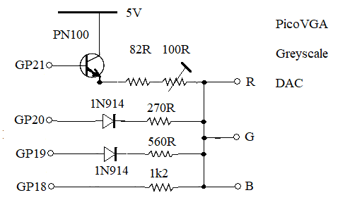
A few people were interested in Grey-scale and RGBI output for the PicoVGA. Here is the Grey-scale installment with a simplified DAC, RGBI to follow also with a simplified DAC.  Adgust the trim-pot to get a uniform scale. The MSB needs more current than is good for a Pico pin hence the transistor. It doesn't need much gain but does need to work at a high frequency. The diodes reduce interaction between pins. The LSB doesn't need one as it's effect is least significant. Below is an array of colour constants to use instead of RGB(xxx) for display commands. They generate the required bits on GP18 (LSB) to GP21 (MSB). The PicoVGA only uses the Most Significant Bits of each of the 3 bytes in the 24 bit RGB values. For red and blue it is 1 bit and 2 for green, the rest of the bits don't affect the output. Eg. GP18 is low for 1 to 127 and high from 128 to 255 (between line and frame blanking periods). Red Green Blue 0 0 0 0 0 252 0 84 0 0 84 252 0 168 0 0 168 252 0 252 0 0 252 252 252 0 0 252 0 252 252 84 0 252 84 252 252 168 0 252 168 252 252 252 0 252 252 252 'Grey-scale Colour Values (Grey(15) = RGB(White)) Dim Integer Grey(15) Grey(0) = 0 Grey(1) = 255 Grey(2) = 21504 Grey(3) = 21759 Grey(4) = 43008 Grey(5) = 43263 Grey(6) = 64512 Grey(7) = 64767 Grey(8) = 16711680 Grey(9) = 16711935 Grey(10) = 16733184 Grey(11) = 16733439 Grey(12) = 16754688 Grey(13) = 16754943 Grey(14) = 16776192 Grey(15) = 16776447 Images must first be processed to convert the colours as the PicoVGA codec expects to output to RGB 1-2-1 hardware. A normal greyscale image will come out B&W on the monitor as black and white are the only grey-scale colours.  This program first makes a normal image then converts it to the format required by this hardware. To keep it simple this is done by loading the image to an LCD screen, reading the pixels, converting the values and writing them back to the screen. One pixel at a time so it is slow! This cannot be done on the PicoVGA as more than 4 bits/pixel are needed. I used an ILI9488 that returns 18 bits/pixel, though it could be adapted for MMB4W for 24 bits/pixel. To convert other colour or grey images delete the first section. It assumes the source image is 320 x 240 pixels. 'Make 320 x 240 pixel 16 level grey-scale image on LCD Dim integer n, m CLS RGB(128,128,128) For n = 0 To 255 m = 255-n Line n+32, 20, n+32, 120, 1, RGB(n,n,n) Line n+32, 120, n+32, 220, 1, RGB(m,m,m) Next Save image "b:/greyscale 4.bmp", 0, 0, 320, 240 'Convert an image for grey-scale hardware on PicoVGA (through the RGB121 Codec) Dim Integer x, y, Ri, Ro, Gi, Go, Bi, Bo, Pix, Mono Load image "b:\greyscale 4.bmp" Pause 500 Toggle = 0.5 For x = 0 To 320 For y = 0 To 240 Pix = Pixel(160-x*toggle,y) 'read back the pixel values 'extract the input colours Ri = Pix >> 16 Gi = (Pix >> 8) And 255 Bi = Pix And 255 Mono = (Ri + Gi + Bi) \ 48 'convert to 16 level greyscale 'Create RGB121 output colours that will decode on grey-scale hardware Ro = (Mono >> 3) * 255 Go = ((Mono >> 1) And 3) * 64 Bo = (Mono And 1) * 255 Pixel 160-x*toggle, y, RGB(Ro,Go,Bo) Next y Toggle = - Toggle Next x Save image "b:/test-VGA-grey-decoder 4.bmp", 0, 0, 320, 240 Print "Image Saved as "+"b:/test-VGA-grey-decoder 4.bmp" End Edited 2023-06-17 22:58 by phil99 |
||||
| lizby Guru Joined: 17/05/2016 Location: United StatesPosts: 3150 |
Thanks for this. I'm away from my hardware for a few more days, but would like to try this when I get back. (Just for LOLs, no serious use case.) PicoMite, Armmite F4, SensorKits, MMBasic Hardware, Games, etc. on fruitoftheshed |
||||
| Mixtel90 Guru Joined: 05/10/2019 Location: United KingdomPosts: 6798 |
Very nice! It's giving good results. Just a couple of ideas if you feel like playing... I wonder if it would be kinder to the Pico outputs to use higher value resistors commoned onto the base of the transistor, which has a single terminating resistor (say, 100R) in its emitter? I've not tried it. GP20 is, in theory, having to source almost 12mA, which is a bit heavy really. It can't actually do that because the outputs have a pin voltage that sags severely under load. Commoning the resistors at the base may be more predictable as they can all get closer to 3V3 too. The transistor, when used in this way, is a current amplifier so there is a lot less load on the PicoMite. Max output voltage would be about 3V3-0.6 = 2V7 so you could even use a tapped resistor in the emitter and come off at about 0.8 to 1V to give a better voltage match. You could probably use a R2R network for more accuracy - if you are fussy. :) Mick Zilog Inside! nascom.info for Nascom & Gemini Preliminary MMBasic docs & my PCB designs |
||||
| Amnesie Guru Joined: 30/06/2020 Location: GermanyPosts: 396 |
This is really great and I have plenty of use for this, thank you! My idea would be to make this switchable via a switch (hardware).. so you can switch between normal operation and grayscale operation. Greetings Daniel Edited 2023-06-18 05:34 by Amnesie |
||||
| Mixtel90 Guru Joined: 05/10/2019 Location: United KingdomPosts: 6798 |
The switch should ideally be 7 pole 2-way, which would be a wafer switch. It may be cheaper to wire up a second PicoMite. :) Mick Zilog Inside! nascom.info for Nascom & Gemini Preliminary MMBasic docs & my PCB designs |
||||
| phil99 Guru Joined: 11/02/2018 Location: AustraliaPosts: 2137 |
Re switching, as I don't have a use for this either I have made plug-in modules on stripboard to keep it simple. Also the reason for not using a proper R-2R DAC. As my PicoVGA is on stripboard adding a socket strip for the modules was easy. For those with PCBs that don't use a 0.1" grid it could be done by replacing the resistors with individual header socket pins and making "hats" to plug in. Re amplification, Started with the transistor on the output but the extra 0.6V offset made it more difficult to get uniform spacing of the grey levels. Change one and it messes up others. The current from GP20 isn't that bad. Total resistance is 270R + 50 (pin Z) + 25 (VGA) = 345 R. Voltage drop is 3.3 (supply) - 0.65 (diode) - 0.25 (output) = 2.65V giving 7.7mA. Also the B-E junction acts as another diode to reduce interaction between pins.  Edited 2023-06-18 14:22 by phil99 |
||||
| Mixtel90 Guru Joined: 05/10/2019 Location: United KingdomPosts: 6798 |
Very nice. :) On an early version of my PicoMite VGA mini I played with using plug-in modules. Because I was stuck for height I used the PCB horizontally, with pins along two edges. It would probably have worked ok but it was a bit of a pig to get it to fit in the case. :) I did wonder about that problem with the transistor. Put current x into the base and the emitter voltage rises. Now how much voltage needs to be added to get a certain change? It depends on where the emitter voltage is at the time. The resistor network is a voltage output, the transistor is current driven. With suitable biasing it may work, probably not worth it though. It just gets more complicated. :) Mick Zilog Inside! nascom.info for Nascom & Gemini Preliminary MMBasic docs & my PCB designs |
||||
| phil99 Guru Joined: 11/02/2018 Location: AustraliaPosts: 2137 |
Here is part two, RGBI Table of colour constants - Number following the colour letter is the bit value. I = intensity. Replace my cryptic names with the colours you see. r0g0b0i0 = RGB(0,0,0) 'low intensity RGB r0g0b1i0 = RGB(0,0,255) r0g1b0i0 = RGB(0,128,0) r0g1b1i0 = RGB(0,128,255) r1g0b0i0 = RGB(255,0,0) r1g0b1i0 = RGB(255,0,255) r1g1b0i0 = RGB(255,128,0) r1g1b1i0 = RGB(255,128,255) r0g0b0i1 = RGB(0,64,0) 'higher intensity RGB - Greater brightness, less saturation. r0g0b1i1 = RGB(0,64,255) r0g1b0i1 = RGB(0,192,0) r0g1b1i1 = RGB(0,192,255) r1g0b0i1 = RGB(255,64,0) r1g0b1i1 = RGB(255,64,255) r1g1b0i1 = RGB(255,192,0) r1g1b1i1 = RGB(255,192,255) You may need to experiment with resistor values to get the effect you want, however this simplified circuit will never be perfect. I tested a couple of much more complicated ones but overall are no better than RGB 1-2-1. With only 4 bits any improvement in one aspect of an image is at the expense of another. Others have produced better image quality using dithering on RGB 1-2-1. The compromise there is that to minimize the "spottiness" you need to view from a distance (or take your glasses off).  'Converting RGB(8,8,8) or RGB(5,6,5) to a version of RGIB(1,1,1,1) 'for display through RGB(1,2,1) codec on RGIB(1,1,1,1) hardware 'using Green low bit (GP19) for Intensity control 'Load an image to the LCD screen before starting. Dim integer I, X, Y, R, G, B For Y=0 To 240 : For X=0 To 320 R = Pixel(X,Y)>>16 G = (Pixel(X,Y)>>8) And 255 B = Pixel(X,Y) And 255 If R + G + B > 255 Then : I = 1 : Else : I = 0 : EndIf If R > 128 Then : R = 255 : Else : R = 0 : EndIf If B > 128 Then : B = 255 : Else : B = 0 : EndIf If G > 128 Then : G = 1 : Else : G = 0 : EndIf G = (G*2+I)*64 If G = 192 Then G = 255 Pixel X,Y,RGB(R,G,B) Next : Next Print "Save the image and transfer it to the PicoMiteVGA" End Edit Sun on the monitor has messed up the colours in the photo. Edited 2023-06-18 16:39 by phil99 |
||||
| Volhout Guru Joined: 05/03/2018 Location: NetherlandsPosts: 4247 |
Hi Phil, Your RGIB has only 9 colors.. Not that it matters. The greyscale may be interesting. When we standardize on this config Peter may even be able to add this to the options, and scale real RGB() values to ti using a lookup table. I myself would be most interested in 16 level greyscale in 640x480, but since memory restrictions force to tiles in this mode, greyscale would be a real pain. Volhout Volhout PicomiteVGA PETSCII ROBOTS |
||||
| phil99 Guru Joined: 11/02/2018 Location: AustraliaPosts: 2137 |
On the monitor I count 16 colours, though the differences are not great. With the intensity bit low:- black, blue, green, cyan, red, magenta, yellow, light grey. With the intensity bit high:- dark grey, light blue, light green, pale cyan, pink, pale magenta, pale yellow, white. The I bit adds brightness to all colours simultaneously, desaturating them. As noted previously it isn't worth the the effort, different but not better. A few others were interested in the idea so now they have a starting point for their own experiments. Edited 2023-06-18 18:53 by phil99 |
||||
| phil99 Guru Joined: 11/02/2018 Location: AustraliaPosts: 2137 |
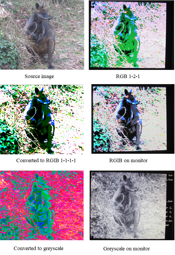
A comparison of the three decoders. In this instance RGBI looks a little better than RGB121 as it can display 2 shades of grey. In some other images RGB121 is better.  However greyscale is best. However greyscale is best. |
||||
| Volhout Guru Joined: 05/03/2018 Location: NetherlandsPosts: 4247 |
Hi Phil, Have you used the dither website to do the conversion? You can select algorithm's how to optimize the resulting picture, and you can feed it a colour pallet. Volhout Edited 2023-06-22 16:39 by Volhout PicomiteVGA PETSCII ROBOTS |
||||
| phil99 Guru Joined: 11/02/2018 Location: AustraliaPosts: 2137 |
Yes, dither does a better job of rendering the colours than the simple colour substitution used above. The tradeoff is effective resolution. you need to be far enough away for adjacent dots to merge to get the correct effect. It is equivalent to the R, G & B sub pixels on a TV screen. There is no yellow, brown, purple etc. It works because the sub pixels are too small to be individually resolved at normal viewing distance. On the PicoVGA Mode 2 they are Big. |
||||
| Volhout Guru Joined: 05/03/2018 Location: NetherlandsPosts: 4247 |
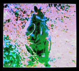
Hi Phil, This is FloydSteinberg on your (grabbed) original picture on Pico RGB-121 in 320x240. Yes, it is noisy, but it is clear what it presents. Volhout Edited 2023-06-22 22:09 by Volhout PicomiteVGA PETSCII ROBOTS |
||||
| Hawk Senior Member Joined: 15/07/2021 Location: AustraliaPosts: 141 |
Thanks very much for posting this @Phil99. I'm interested in trying the RGBI version. I think that having the extra greys will give some extra options for pixel art. The changed palette is also very similar to the ZX Spectrum...not that it was the best palette in the world, but pixel artists have been able to come up with some amazing creations within the limitations of the ZX Spectrum palette. I'd be intersted to know what values I should try to increase the difference between the low intensity and the high intensity colours. Mike |
||||
| Volhout Guru Joined: 05/03/2018 Location: NetherlandsPosts: 4247 |
This is RGIB-1111 mode dithered. For some reason it looks not as good as RGB-121. But that may be this particular picture that does not match with the palette. PicomiteVGA PETSCII ROBOTS |
||||
| phil99 Guru Joined: 11/02/2018 Location: AustraliaPosts: 2137 |
Here is what the RGB121 dithered one looks like on the Pico.  The settings for dithering may need optimizing. Perhaps before dithering the size needs to be 320 x 240 pixels or less. When I resized the dithered image to fit the Mode 2 screen it probably messed up the dithering. Edited 2023-06-22 23:05 by phil99 |
||||
| phil99 Guru Joined: 11/02/2018 Location: AustraliaPosts: 2137 |
@Hawk The requirement is for 700mV output with both colour and intensity pins high. That is achieved when the parallel combination of the 2 resistors that go to each VGA pin is 250 ohms. 560R || 470R is close. 680R || 390R may also be worth a try. EDIT No, going senile. 910R is the minimum for the I pin as there are 3 in parallel. You could add a transistor connected the same as in the greyscale circuit to drive lower values, however lower values will make the colours very pale. The solution is to add a transistor||resistor in series with each of the colour pins, controlled by the I pin. Tried this when Mode 2 was first introduced but didn't consider it any better than RGB121. Edit 2 Here is the circuit, as best I can remember. The RGIB image converter will need to be changed to match the different circuit, after the values of the variable resistors has been set. The individual 8 bit RGB(r,g,b) values correspond to the VGA pin voltages - 0 to 255 = 0 to 700mV. So by measuring the output voltages on a scope for all 16 colours you can see what values are needed in the converter program.  Without the optional Grey circuit there are 2 Blacks so only 15 colours. It turns Black Low intensity to grey, Black High intensity remains black. Edit 3 More testing of dithering. Mode 2 pixels are just too big. No matter what settings I use the improvement in colours is insufficient to compensate the loss of resolution. The Pico just does not have enough memory to make the pixels small enough for this to be acceptable. Edited 2023-06-23 22:41 by phil99 |
||||