|

|
Forum Index : Microcontroller and PC projects : PicoMite: ILI9341 wiring
| Author | Message | ||||
| thwill Guru Joined: 16/09/2019 Location: United KingdomPosts: 4047 |
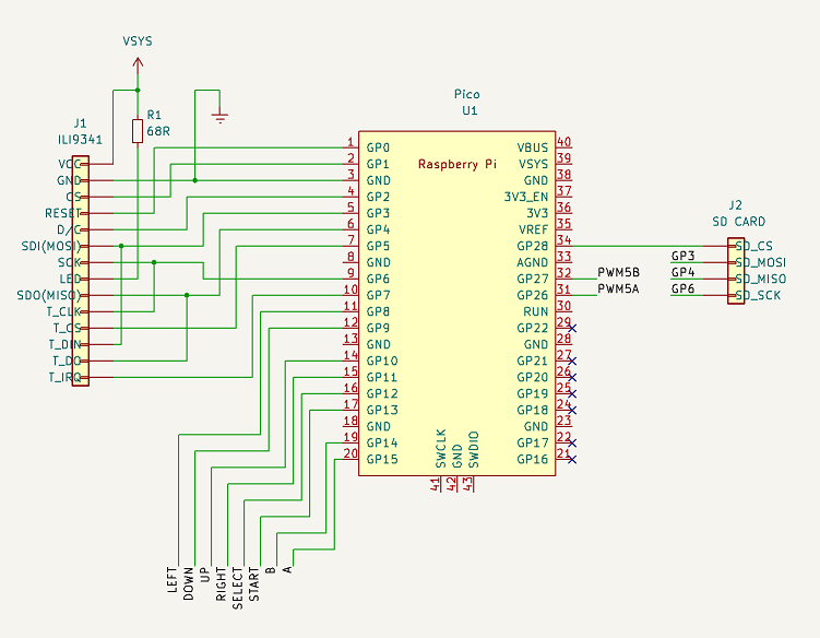
Hi folks, I'm finally moving forward on building a v2 prototype for my PicoGAME LCD hand-held (aka Bintendo Lameboy) and I was wondering if someone would be generous enough to validate that I'm proposing to wire up the ILI9341 correctly (this is the first time I've had to do it for myself because the v1 prototype just copied the pin allocation on @Mixtel90's original PicoMite backpack).  Notes: 1. The display is sitting astride the "surface mounted" Pico. 2. There is no shift register for the inputs this time since the Pico has plenty of free pins. 3. I'll probably take the spare pins GP16-22 out to a header. Thanks in advance, Tom Game*Mite, CMM2 Welcome Tape, Creaky old text adventures |
||||
Quazee137 Guru Joined: 07/08/2016 Location: United StatesPosts: 573 |
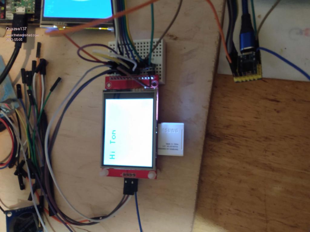
Looks good to me you could even get away using the tiny waveshare RP2040 Zero. Now looking for my box of displays to have a play adding the ILI9341 to RP2040 I am playing with it currently has a ILI9481 no SD so FUN to be had. Quazee137 |
||||
| Mixtel90 Guru Joined: 05/10/2019 Location: United KingdomPosts: 6805 |
I've just got some RP2040-Zero modules. Really cute! :) Getting one to surface mount would be a right pain though, having to cut a hole or holes in the pcb so that it could sit flush. That does away with being able to run tracks underneath it or mount something on the other side of the board. Not breadboard friendly either, if you fit the five end pins in the same direction as the others. Mick Zilog Inside! nascom.info for Nascom & Gemini Preliminary MMBasic docs & my PCB designs |
||||
| lizby Guru Joined: 17/05/2016 Location: United StatesPosts: 3152 |
Tom--there may not be any likelihood that you will ever want to use an ILI9488 (480x320), but if there is a possibility, you might want to wire PicoMite MISO directly to T_DO and then with a 680 resistor to LCD MISO. (In your diagram, if you move your junction to T_DO to the right, you can probably cut the line to LCD_MISO and insert the resistor.) That should work with either ILI9341 or ILI9488. Otherwise, it looks good to me and MISO, MOSI, and SCK look to be using the correct pins, which is the critical hardware issue. PicoMite, Armmite F4, SensorKits, MMBasic Hardware, Games, etc. on fruitoftheshed |
||||
| Hans Senior Member Joined: 18/10/2022 Location: CanadaPosts: 116 |
@thwill Just want to say I'm not complaining about your wiring but ... This is not the same as presented in the manual on page 48. Just curious why this way and not as the manual suggests? Hans ...  |
||||
Quazee137 Guru Joined: 07/08/2016 Location: United StatesPosts: 573 |
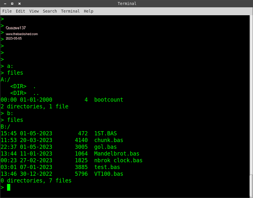
Tom it works OPTION SYSTEM SPI GP6 GP3 GP4 OPTION SDCARD GP28 OPTION LCDPANEL ILI9341, L, GP2, GP0, GP1 OPTION TOUCH GP5, GP7   Quazee137 |
||||
| Mixtel90 Guru Joined: 05/10/2019 Location: United KingdomPosts: 6805 |
I think Tom has got that wiring from my PicoMite Backpack design. It doesn't matter which SPI port is used or which pins for that port are used as they are all specified in the OPTION commands. This is one of the beauties about the PicoMite - there are no dedicated pins so you just use the ones that fit your PCB layout the easiest. :) Programs don't know or care which pins are being used, they simply send a command to draw a line or something and MMBasic sorts out all that stuff. To sum up, there are no "correct" pins other than you must use those that are capable of the use that you want. The manual shows working examples, but that's all they are. Mick Zilog Inside! nascom.info for Nascom & Gemini Preliminary MMBasic docs & my PCB designs |
||||
| IanRogers Senior Member Joined: 09/12/2022 Location: United KingdomPosts: 151 |
Just remember that the SD slot built into those screens have 1k resistors on the MOSO, SCK and CS.. I had to remove them or the SD wouldn't work. You probably will use a different SD as you need it accessible. I'd give my left arm to be ambidextrous |
||||
| Mixtel90 Guru Joined: 05/10/2019 Location: United KingdomPosts: 6805 |
You can always use the display upside down and access the SDcard from the top. :) Mick Zilog Inside! nascom.info for Nascom & Gemini Preliminary MMBasic docs & my PCB designs |
||||
| thwill Guru Joined: 16/09/2019 Location: United KingdomPosts: 4047 |
Thanks folks, Thanks! Actually building and testing it for me goes "above and beyond"  . .I'm planning on using the standard PicoMite module (even if it pokes out a bit from under the display) and I'm going to sit it on some male pins rather than surface mount it so that there is enough clearance to plug the USB in ... and just enough so the SD card doesn't interfere with the USB plug either. Thanks Lance, but I'm assuming those modules have a different footprint so I don't see that being worth doing; any PCB would already have to be significantly hacked and what's one more flying resistor between friends. That is what I figured. QUESTION: What about CS, can that be any pin ? Looking at a Pico pinout diagram some of the pins are tagged CSn0 and CSn1, but where multiple devices are connected to the same SDI (i.e. LCD and Touch and SD card) doesn't each device on an SDI require a unique CS ? As Mick indicated the Pico/PicoMite allows some flexibility in pin allocation so I've laid it out in what I hope is an optimal configuration (short wires, minimal crossing) for the Bintendo. The wiring of my original v1 was a bit of a rat's nest because I just used the same wiring as the PicoMite backpack even though orientation of PicoMite and LCD were different. True for the v1, not for the v2. It's accessible where it is, at the top of the device, though I might be inclined to remove it and bodge a micro-SD in its place because they don't stick out so much. The resistor issue seems to vary, I had to short them on an earlier (non-touch) display that I have since killed with static, but the SD card on my newer (touch) display seems to work fine with the resistors in place. Snap! How convenient that the firmware allows both LANDSCAPE and RLANDSCAPE configuration. QUESTION: When adding a reset button (RUN => GND) is a small series resistor advisable ? Best wishes, Tom Edited 2023-05-05 20:45 by thwill Game*Mite, CMM2 Welcome Tape, Creaky old text adventures |
||||
| stanleyella Guru Joined: 25/06/2022 Location: United KingdomPosts: 2129 |
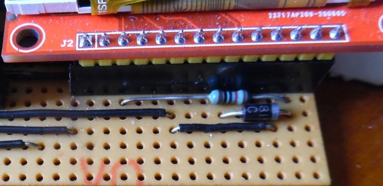
I used vero to mount ili9341 and ili9488 and used 2 male sockets for the sdcard pins so the displays are swappable. I used a resistor and diode to make the ili9488 work. Nothing was needed for the ili9341, it all just worked.   |
||||
| IanRogers Senior Member Joined: 09/12/2022 Location: United KingdomPosts: 151 |
Bit like those frequency generator boards.. some are 100ohm some are 1k others are 10k. Lucky dip from China... I'd give my left arm to be ambidextrous |
||||
| Mixtel90 Guru Joined: 05/10/2019 Location: United KingdomPosts: 6805 |
You can have a plug-in PicoMite underneath a LCD display, but not with the usual headers. If you use the little turned-pin sockets (short version) that are sometimes used for ICs and the male headers for them then it works nicely. There is still enough space under the PicoMite to mount resistors too. :) The CS lines for SPI on the PicoMite can be any pin as they are specified in OPTION for each device. RUN input doesn't need a series resistor as it can never be an output. Mick Zilog Inside! nascom.info for Nascom & Gemini Preliminary MMBasic docs & my PCB designs |
||||
| phil99 Guru Joined: 11/02/2018 Location: AustraliaPosts: 2140 |
"RUN input doesn't need a series resistor as it can never be an output." What can be useful is a small capacitor (10nF to 100nF) from RUN to Gnd. to prevent random resets. |
||||
| Hans Senior Member Joined: 18/10/2022 Location: CanadaPosts: 116 |
@All; Thanks for the explanations. I think I was going on the assumption that if it was in a piece of documentation that that was the preferred method. I can see now that the versatility of the OPTION declarations make it irrelevant as to the layout. What great software Peter and Geoff have given us for these versatile little PICOs.  Thanks All, Hans ...  BTW I bought a PicoMite03 board the other day and I'm really having fun with it!  |
||||