|

|
Forum Index : Other Stuff : Smart Drive Hydro Water Wheel
| Author | Message | ||||
| KennyG Newbie Joined: 06/03/2017 Location: United StatesPosts: 12 |
I'm 54 and finally got to my hydro project . I recently got a Samsung 36 pole smart drive and realized it is wound with aluminum wire , so I'm going to rewind it. First , for my circumstance, should I use 18 ga wire ? How many turns should I do ? Which wiring configuration should I use ? I want to do the lowest RPM, with the most power . I have a 24 v system . Also I was reading that someone in the forum was doing a lot of research with capacitors configured with the smart drive . Do I use them on the 3 phase AC or after the rectifier on the DC? How many and what size ? Appreciate any help . Thanks From my research so far , I think I need to do 42 turns of 18 ga wire on each pole and wire it in the 2x6c configuration . If I am wrong , please let me know . I still am baffled about the capacitors . Thanks again , Kennyg Well, The more that I read, the more I wonder if I should keep it like factory , 1x12c. Since it's a water wheel , and I want the lowest RPM possible . I found the content on Gordons caps, THANK YOU Gordon !! I now understand it. I still am deciding what size to start out. Any input would be appreciated ! Kennyg |
||||
| ryanm Senior Member Joined: 25/09/2015 Location: AustraliaPosts: 202 |
As it's a water wheel you'll almost certainly have to gear the output to get the Samsung to turn at a speed appropriate to generate power. The winding configuration depends on the final RPM. Here's a site with a bunch of info on micro hydro systems that you might find useful. There's a page on there just about low head systems like water wheels. http://www.builditsolar.com/Projects/Hydro/hydro.htm Have fun. |
||||
| weswooly Newbie Joined: 02/09/2017 Location: AustraliaPosts: 4 |
How is your hydro project going? What did you end up doing? I am going to attempt a similar project soon so any lessons you learned along the way I'd be glad to hear about :) |
||||
| Warpspeed Guru Joined: 09/08/2007 Location: AustraliaPosts: 4406 |
I recently needed to replace the broken drive belt in my tumble dryer. This uses a rather nice thin flexible multigroove belt that might make an ideal drive for stepping up the speed of a slow turning waterwheel. The tumble dryer drums are typically around 500mm to 560mm diameter, and the typical motor pulley 19mm diameter. The problem with such a large ratio is there is not usually much belt wrap around the smaller pulley. Even with a dry belt, its likely to slip unless the belt is kept very tight. Multigroove pulleys and belts are ideal for something like this, they don't slip even if not particularly tight, and the belts are very flexible to go around the smaller pulley. They are also commonly available from e-bay in various (but fairly similar) lengths. There will also be a spring tensioning system in the dryer that may possibly be reused. In a dryer there may be a 1,450rpm four pole motor, a ratio of roughly 30:1 producing a drum speed in the region of 45 to 50 rpm. A water wheel might turn rather more slowly, but approximately 30:1 pulley ratio might be useful. One further thought. BMX bike wheel rims are commonly 20 inches (500mm) and would be about right for the larger pulley. Just another idea.... Cheers, Tony. |
||||
| KennyG Newbie Joined: 06/03/2017 Location: United StatesPosts: 12 |
Hello , My project is going a bit slow . I got my Smart drive rewound and I'm working on my wheel . I'm using a 50 gal. drum, which I cut and made 10 paddles . I ripped 6 inch pipe lengthwise and attached to that . I am ending up with a 4 ft diameter , 3 ft wide wheel . I'm putting it in a stream . I put a 24 inch rim on the wheel, and using a cogged timing belt to a cogged gear . I figure at the least I'll get 10 - 15 rpm . I want at least 500 at the generator . I may have to gear it up some . I'll keep you advised . Like to be done before the snow falls here in Pennsylvania . Thanks , Kenny G |
||||
| Warpspeed Guru Joined: 09/08/2007 Location: AustraliaPosts: 4406 |
That sounds pretty good Kenny. Its going to need a fairly high speed step up ratio, and that may be better to do it in two stages. The trick for making it much easier to turn seems to be not to make the small pulleys too small in diameter. That seems to be the big problem with using speed reducing gearboxes as speed increasing gearboxes. Going down in speed, you can use an incredibly small pinion to drive a very large gear, and that will work fine. But trying to drive something like that back the other way is not going to work very well. If you need say 50:1 it may be more efficient to use two stages of around 7:1 Cheers, Tony. |
||||
| KennyG Newbie Joined: 06/03/2017 Location: United StatesPosts: 12 |
Hey there Tony , That's exactly what I was thinking also . I figured two stages will work . If I think I have more power I thought I could add a third stage and increase the rpms more . I'll keep you posted . Thanks again , Kennyg |
||||
| Warpspeed Guru Joined: 09/08/2007 Location: AustraliaPosts: 4406 |
High rpms by themselves are not really an advantage. But pulley ratios and the various multiple ways you can connect up a smart drive alternator give you plenty of options to play around with. The only way you are going to optimize the setup is by experimentation. Cheers, Tony. |
||||
| bitdog Newbie Joined: 13/11/2016 Location: United StatesPosts: 15 |
This stuff might be good advise. You decide..... Wire your alternator after it's working to a voltage just above what you want. Do not rewire in copper your F&P, just use it as it is. If one F&P is good, two is better. If your water wheel puts out more than a half a horse power, consider a double F&P configuration. Higher RPM = higher voltage. V belts waste power. Notice they are not used on bicycles, that have limited power and don't want to waste power. Bicycle gearing, chains, bearings, etc are thrown out at our garbage dump every day, & I get them for free, in bulk. Use that stuff.... If your F&P is above your water wheel shaft, your drive chain pulls down between the shaft and the water weight = efficient.... Old water wheels designs for powering a shop in the 1800's or so, had a gear on the outer rim, and a small gear to that, ran a high speed shaft into the building. So weld a chain to the rim of your water wheel and use a bicycle gear on the F&P shaft, on the side where the water falls down... There might be something worth considering in this gibberish.... Bitdog |
||||
| Warpspeed Guru Joined: 09/08/2007 Location: AustraliaPosts: 4406 |
Bike chains rust fairly readily, even on a bike. They are otherwise excellent in every other respect and would be an excellent choice, especially if the chain can be enclosed and dips into some kind of oil filled sump. The rubber toothed "timing belts" will not slip and have all the advantages of a chin, except for cost. The larger pulley probably will not need teeth, and should not slip simply because of the very large contact area. Its always the smaller pulley that is the problem. A very slim flexible toothed belt, around a toothed plastic pulley will be as efficient as a chain without the rusting up problem. Cheers, Tony. |
||||
| KennyG Newbie Joined: 06/03/2017 Location: United StatesPosts: 12 |
Hello again , I went with a 24 inch bicycle rim on the wheel . I have a microgroove serpentine belt running to a 2 inch alternator pulley on a shaft. I have an idler pulley right at the 2 inch pulley, with a spring tentioner. I then have a 40 tooth chain socket on the shaft. Then a 15 tooth on the PMG. If I only have 10 rpm on the wheel , I'll have approximately over 300 rpm on the PMG. I got to try it once without a load connected and it seems it will work pretty well . Then the weather got bad . Been in the teens, F |
||||
| KennyG Newbie Joined: 06/03/2017 Location: United StatesPosts: 12 |
Sorry , The creek is frozen . I'll have to wait till it thaws now . Thanks KennyG |
||||
| Warpspeed Guru Joined: 09/08/2007 Location: AustraliaPosts: 4406 |
Sounds really good Kenny. Nice and sunny here in Australia, not too hot yet, nice balmy weather. Cheers, Tony. |
||||
| BobD Guru Joined: 07/12/2011 Location: AustraliaPosts: 935 |
Tony, You can't be too far away from me. We are forecast to have 41 Celsius tomorrow. That's nice and balmy. Bob |
||||
| Warpspeed Guru Joined: 09/08/2007 Location: AustraliaPosts: 4406 |
Yes I was just looking at that Bob. Think I may hide indoors and turn on the air conditioner tomorrow. Cheers, Tony. |
||||
| kvnrschmdt Newbie Joined: 15/05/2018 Location: CanadaPosts: 2 |
Hi KennyG, Did you keep your stator "factory" - at 1x12C? Or did you rewire it? Just wondering, because I'm building a hydro generator with a jet/pelton wheel, and I'm wondering the best way to rewire my 35 pole stator. Curious how its going, now that spring has come. Cheers, Kevin |
||||
| Warpspeed Guru Joined: 09/08/2007 Location: AustraliaPosts: 4406 |
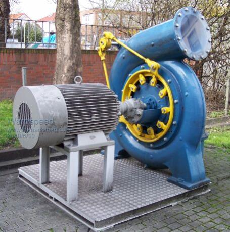
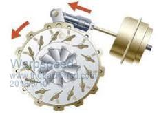
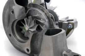
Jet/pelton wheel is simple, but I wonder if something a lot more efficient might not be possible. Problem with a Pelton wheel is only one pair of buckets are producing useful torque at any instant. Thats fine, as long as the water head pressure is quite high which may sometimes be difficult. In a real full sized commercial hydro, the answer is the Francis turbine which uses a snail shaped housing and a very carefully shaped turbine wheel which produces constant torque from every blade all of the time. They also commonly use guide vanes to adjust speed and torque to match the load. Here is a fairly small example of a Francis turbine fitted with guide vanes:  Now the really interesting thing about all of that, is that the internal geometry of a Francis turbine, is identical to the internal geometry of a turbocharger exhaust turbine. They essentially do an identical job. A lot of R&D goes into development of turbo exhaust turbines and the shape and fit into the housing is about as perfect as is possible. Not only that, the turbines and housings are made of stainless steel alloys and will not rust. Turbine housings are available in a wide variety of sizes with different nozzle areas (A/R ratios) which can be interchanged to match the head pressure and flow you have available. An even better solution to finding a suitable exhaust housing A/R by trial and error, would be to use guide vanes similar to a real Francis hydro turbine. A variable vane turbocharger turbine would be ideal, as its already all there...  Should not be too difficult to pack the bearings with waterproof boat trailer wheel bearing grease, and fit some toothed pulleys to drive the alternator. It would be a case of removing the aluminium compressor wheel (on the left) which has a smooth bore, with a toothed pulley (on the right) that can also have a smooth bore in the same position on the shaft. There is a left handed nut on the end of the shaft which tightens if the pulley tries to slip. The whole job looks to be fairly straightforward requiring only simple tools.  Cheers, Tony. |
||||