
|

|
Forum Index : Other Stuff : Building a Spot Welder
| Page 1 of 2 |
|||||
| Author | Message | ||||
| Gizmo Admin Group Joined: 05/06/2004 Location: AustraliaPosts: 5078 |
Hi all. After reading Vasi's thread on home made welders built from microwave oven transformers, I got the idea to make a spot welder. Lately I've been making a few tools for the workshop, and having access to a laser cutter has make the job easy. Below is my disc sander and belt sander, using old induction motors I've had sitting on the junk pile for may years. 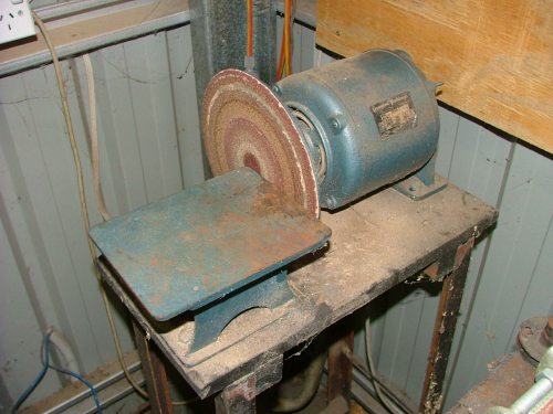
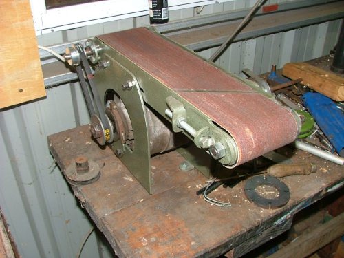
Next is a spot welder. I already have a mig welder, but a spot welder is so easy to use on those quick light steel jobs. I found a heap of info on the internet on home made spot welders using microwave transformers, but I wanted something with a little more grunt. I found this PDF http://www.green-trust.org/junkyardprojects/FreeWelderPlans/ SpotWelder%232.pdf which describes an old machine, but old is good. 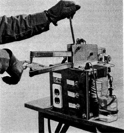
A quick search through the junk pile turned up an old Nikko UPS with a dirty great transformer inside. I cut off the secondary winding with a hacksaw, then wound some heavy welding wire around the primary. A quick test showed 4.2 volts AC output, perfect! Next I'll make up the clamp arms with brass tips, and the control circuit. For control, I was going to use a NE555 timer so I could adjust the weld period to get consistant results, fired by a foot switch. The lighter is there for size comparison, since I gave up smoking I seam to have lighters everywhere 
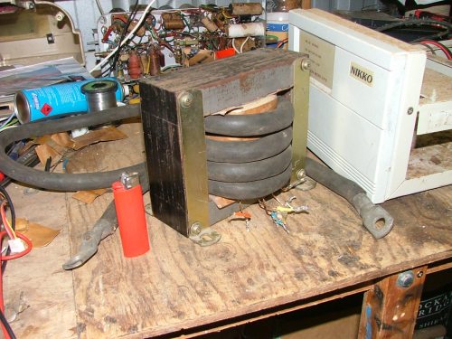
So any idea's or input would be appreciated, I havn't used a spot welder for over 20 years so if anyone has a few tips on use or construction I would appreciate it. Glenn The best time to plant a tree was twenty years ago, the second best time is right now. JAQ |
||||
| Gizmo Admin Group Joined: 05/06/2004 Location: AustraliaPosts: 5078 |
I drew up and lasercut parts for the spot welder "pincher" today. The parts were cut from 12mm and 5mm steel plate. 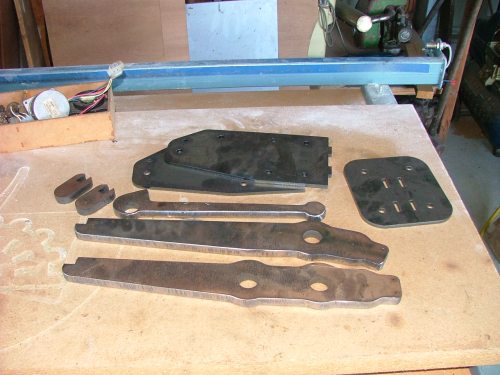
Once I got the parts home, I used the side plates as templates to cut some 3mm fibreboard. The laser can cut this stuff, but its messy and leaves a carbon rich burnt edge. As this fibreboard was to be used as a insulator, I didn't want any carbon edges, so it was easier to cut the fibreboard manually. I also used a hole saw to make up some washers. 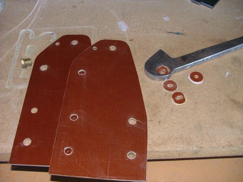
A bit of welding, and I put the bits together as a mock up to make sure it will work. Looks good. 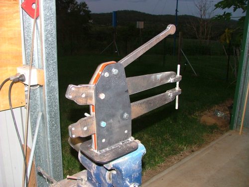
The lever at the top is to clamp the tips together, I need to add a sping at the back to pull the tips apart. Glenn The best time to plant a tree was twenty years ago, the second best time is right now. JAQ |
||||
| dwyer Guru Joined: 19/09/2005 Location: AustraliaPosts: 574 |
Hi Gimzo  Bloody good ideas about spotweld as l all way want one and never through about mirco waves transformer however l work for a company and built Australia made stud welder that useing copacitor discharge when i was electronic wireman at the time around 1968 in melbourne anyway l can get many tranformer if the rubbish tip for free Glenn let me know if you need some regard ian Bloody good ideas about spotweld as l all way want one and never through about mirco waves transformer however l work for a company and built Australia made stud welder that useing copacitor discharge when i was electronic wireman at the time around 1968 in melbourne anyway l can get many tranformer if the rubbish tip for free Glenn let me know if you need some regard ian     |
||||
Gill Senior Member Joined: 11/11/2006 Location: AustraliaPosts: 669 |
G'day Glenn, That'll be a good sized unit when it's finished. I scored an old mini spot welder 6 months ago. I checked it out and mostly seems fine. The only fault seems to be 2 x 480MFD caps the worst for wear. Tried to substitute a couple of junk box caps of much larger capacity but poor result. I feel it is made for say spotting the tabs on batteries. Very small stuff. Could not do a broken off sausepan handle lug. Fell off before it made it to the kitchen. Tried to find the circuit diagram I made of it but the gremlins have hidden it.(Their favorite game at my place). As I recall, there were 2 transformers. An initial voltage drop and current boost with 4 selectable voltages. This charged up the two big caps. Then, only when the pincers are clamped together can the WELD button be pressed. This disconnects the caps from incomming voltage and shorts them through the second High current transformer(primary). The secondry of the high current tranny is a circuit through the pincers. And Voila... Zitt ! So you'll have to post your circuit and modified components list too. Yeh? Mine has heavy braid wire supplying both pincer arms of brass with pincers of copper. With your arms of steel, will you run a braid wire along the arms to the pincers or will the steel arms carry the current? And what are the pincers (I don't know the real trade name for them but pincers sounds perfectly descriptive to me)to be made of? Looking good so far. was working fine... til the smoke got out. Cheers Gill _Cairns, FNQ |
||||
| Gizmo Admin Group Joined: 05/06/2004 Location: AustraliaPosts: 5078 |
The circuit for mine will just consist of a one shot NE555 timer with a duration adjustment on the front case. This will switch a contactor in series with the transformer. The transformer itself has two primary windings ( actually they were the secondary windings when it was a UPS ), If I connect them in series I get just over 2.1 volts on the secondary, in parallel I get 4.2. I'll use a Hi Low switch so I can change between the two combinations. I figure with the Hi Low switch and timer I should be able to adjust the machine for any thickness up to say 1mm plate. I did intend to make the arms from aluminium, but a phone around this week and every single bloody steel merchant or aluminium welder in this town is closed for the Christmass period  So I went for 12mm steel, and added a lot more cross sectional area to help cary the current. I think it will be ok, see how it goes. If the steel gets too hot I'll buy some more welding cable and run it straight to the tips. The tips in the picture are there just for show, I need to buy some brass thread, or even copper if I can find it. So I went for 12mm steel, and added a lot more cross sectional area to help cary the current. I think it will be ok, see how it goes. If the steel gets too hot I'll buy some more welding cable and run it straight to the tips. The tips in the picture are there just for show, I need to buy some brass thread, or even copper if I can find it.
Glenn The best time to plant a tree was twenty years ago, the second best time is right now. JAQ |
||||
| Gizmo Admin Group Joined: 05/06/2004 Location: AustraliaPosts: 5078 |
I should add, if anyone wants a copy of the DXF file I used to cut the parts then let me know. But I would wait to see if it all works first. Glenn The best time to plant a tree was twenty years ago, the second best time is right now. JAQ |
||||
| herbnz Senior Member Joined: 18/02/2007 Location: New ZealandPosts: 258 |
Hi Glen In welding transformers the output current is limited by the loose coupling between the pri and sec windings. If you find you draw to much current try sec winding 1/2 on each outer leg core. I have a small portable unit here that is very handy it has the handle controlling initial clamp then weld not timed you just observe then press harder and it shuts current off and holds pressure on. I could if you wish remove covers and take pic to show how it is set up. Herb |
||||
Gill Senior Member Joined: 11/11/2006 Location: AustraliaPosts: 669 |
Glenn, By my estimations you're expecting to get from 850 to 1500 amps per Zapp, is this about right for these things? I'm thinking the primary of an UPS would be a fairly solid wire, this doesn't seem the kind of project a microwave transformer would be suitable for. Maybe a smaller version more like mine? Two in parallel might be better. I don't expect I could run one of these designs because I'm off grid and the generator protests every time the arc is struck with the welder. Always a lag for the revs to build up to max before you can settle in to the weld run. I can supply a saucepan and handle for the test run if you're short of jobs. Ha.ha. was working fine... til the smoke got out. Cheers Gill _Cairns, FNQ |
||||
| Dinges Senior Member Joined: 04/01/2008 Location: AlbaniaPosts: 510 |
Hello, My first post on this board but have been reading for a while. A few months ago I built a small spotwelder too, using an old microwave transformer. I really wanted to build a capacitor discharge spotwelder (see links below) but don't have the right caps at the moment (~1F @ 30-40 V), so decided to make a transformer spotwelder first. It uses an old microwave transformer, a NE555 timer with front timing potmeter, driving an Opto22 solid state relay. Schematic can be found here: http://www.anotherpower.com/gallery/dinges/spotwelding_machi ne?full=1 Here are some photos of the welder (without the clamps), I used an old welding inverter case (which already had convenient welding fast-connect connectors. http://www.anotherpower.com/gallery/dinges?page=13 It works, but only for very thin stainless steel metal as the current is too small (~500A); I have too much resistance in the connecting wires. I plan to build a new, bigger one when I can find a suitable 2 kVA transformer with inner primary (and an easy to remove secondary). The new one will have the welding thongs connected straight to the transformer, without wires. Resistance kills quickly in this application (I think my total wire resistance was 12 milli-ohm, which limited current to ~500 A). Here are some links to other projects, for those interested: http://www.5bears.com/welder.htm http://www.philpem.me.uk/elec/welder/?elec/welder http://sunstoneengineering.com/site/pages/products (products that make me drool...) I'll be following your experiments with interest! Peter D. |
||||
| Gizmo Admin Group Joined: 05/06/2004 Location: AustraliaPosts: 5078 |
Thanks for the links Peter. Finished the welder today. Made a foot switch from some 1mm zinc plate and a couple of DSE switches. 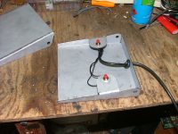 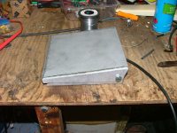
Below is the circuit, I need to draw it up. It uses a NE555 as the timer. I had to add a lot of spike protection, the back emf from the contactor and transformer was causing false triggering. I still need to tidy up the wires with cable ties. 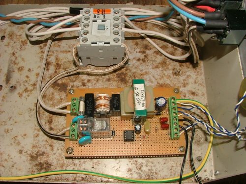
The finished machine. 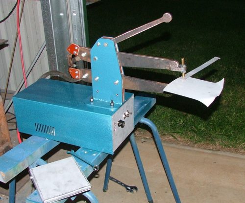
And some test welds, 1mm zinc plate. 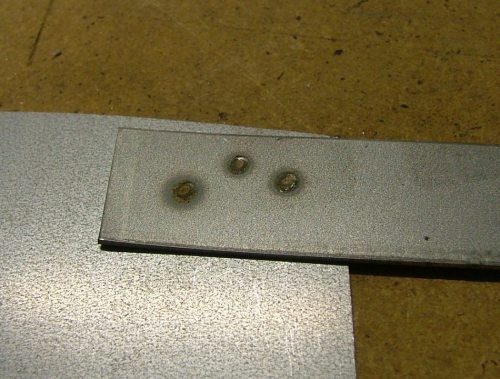
I do need to replace the steel arms with aluminium, the steel gets very warm after a couple of welds, and this means I'm loosing a lot of the available energy in the arms. Glenn The best time to plant a tree was twenty years ago, the second best time is right now. JAQ |
||||
| vasi Guru Joined: 23/03/2007 Location: RomaniaPosts: 1697 |
Great job as usual. How strong is the "connection" between plates? Maybe the schematic will have his page on info/projects ? Hobbit name: Togo Toadfoot of Frogmorton Elvish name: Mablung Miriel Beyound Arduino Lang |
||||
| Tinker Guru Joined: 07/11/2007 Location: AustraliaPosts: 1904 |
May I suggest not to bother with alu arms as your results will even then still lack 'ummph'. Try to get some suitable size flat braid copper and connect it directly to the back of the tip electrodes. As was mentioned elsewhere in this thread, resistance in the wrong places kills a spot welder. Ideally, you want 99.99% of the resistance at what's clamped between the electrodes. Commercial small spot welders I used (years ago) had about 25mm dia copper rod for the pincer arms, one even had the arms water cooled. Klaus Klaus |
||||
| Dinges Senior Member Joined: 04/01/2008 Location: AlbaniaPosts: 510 |
Glenn, Not sure if you know this, but there's a very easy way to measure those low resistances (milli-ohms) using an ordinary DMM set to the 200 mV range. All it takes is a car battery and a H4 bulb (12V, 55-60W car headlight). Wire the bulb to the battery, but use the welder to complete the circuit. Measure the current that flows, let's say 4 A. Now, take the DMM and measure the voltage between two points of which you want to know the resistance (for example, on both sides of crimp joint, or two ends of the pincer arms). Let's assume you measure 2 mV. Then one can work out the resistance of the joint using Ohm's law: R=U/I = 0.002/4 = 0.5 milli-ohm. It's basically a variant of the Kelvin 4-wire measurement system, eliminating the resistance of the test leads. One can make very accurate measurements of low resistances that way. It might help to determine where you have (too much) resistance in your spotwelder and what things must be improved first. If it's not clear let me know and I'll make a quick sketch of what I mean. I have built a little meter that just does the above, with a 1 A current source (saves having to do the math) and a 200 mV digital voltmeter display, giving a readout calibrated in (milli) ohms; see the three pictures on the 2nd row: http://www.anotherpower.com/gallery/dinges?page=2 Peter. |
||||
Trev Guru Joined: 15/07/2006 Location: AustraliaPosts: 640 |
Glenn, Sometimes I think I don't anything, compared to what you guy's know. Excellent work. I could use those steel arms as a pattern and cast in aluminium, brass, silicon or manganese bronze, or copper! Silicon or Manganese Bronze would be my pick as they are high copper content, but with the other alloying metals, makes them very strong. Pure copper is soft. Trev @ drivebynature.com |
||||
| Gizmo Admin Group Joined: 05/06/2004 Location: AustraliaPosts: 5078 |
Thanks for the input guys. Tinker I already converted it over to aluminum arms before I read your post, bugger. I used two lengths of 25mm dia aluminum, big improvement. But the project is on hold for a week or two, got a few jobs needing my attention. I had to change the air conditioner evaporator in my car, what a job, took all weekend to remove the entire dash and climate control unit. Would have been easier to change the engine spark plugs via the exhaust tail pipe. 
Back to the welder, I was having problems with the 555 timer circuit, false triggering and unreliable duration, I think a lot of its from the back emf and slow response of the contactor, so I'm replacing the contactor with a couple of Triacs. Also kept blowing 10 amp fuses, I need to get some slow blow types. Will let you know when I get back to it. Glenn The best time to plant a tree was twenty years ago, the second best time is right now. JAQ |
||||
| wind-pirate Senior Member Joined: 01/02/2007 Location: CanadaPosts: 101 |
http://www.geocities.com/aaawelder/ Try this link. this welder is made from two old micro waves. If you wind them right they will weld small items quite well. Ron THE Pirate. stealing wind & solar energy is fun |
||||
| maestro19 Newbie Joined: 28/01/2008 Location: AustraliaPosts: 1 |
Hi All, First post here I took this today: 
The poster ate my first two post attempts, so I'll just put this up and go for more content later... (edit) Ah, figured it out. Anyways, yeah - my spot welder will emphasise a short low-resistance path to the electrodes, and as much copper as possible in the secondary winding. I couldn't get that blue beast in there for even a second turn, so the plan is so strip out the multicore bundles (of which there are 19) comprising the cable core, select about half of the bundles, wrap that in vinyl tape / shrinkwrap, then stick that in the transformer. I suppose I could try to make the new cable flat instead of round to aid in winding... not sure, these are early days.  |
||||
| Gizmo Admin Group Joined: 05/06/2004 Location: AustraliaPosts: 5078 |
Hi Maestro19, welcome to the site. I bought some welding electrode wire for my transformer. I found it had two layers of insulation, so I peeled off the outside layer, and this give me enough clearence to fit an extra turn around the transformer. I ended up running two windings, of 5 turns each. These were then connected in parallel at the electrode arms. I finished the welder this weekend, its a working unit but still needs a little tuning. Glenn The best time to plant a tree was twenty years ago, the second best time is right now. JAQ |
||||
| Dinges Senior Member Joined: 04/01/2008 Location: AlbaniaPosts: 510 |

After procrastinating for a few years I got inspired by this thread to finally build a capacitor-discharge spotwelder. My previous spotwelder, built around a microwave transformer, wasn't a big succes, but the CD welder is ! http://www.anotherpower.com/gallery/album92 It basically consists of a large bank (1.564 F) of capacitors that gets discharged through the workpiece via a large thyristor (SCR). The sudden flow of high current heats up the joints enough to make a weld. It was originally only intended to weld thin (0.003-0.005") nickel strips to batteries, to make and rebuild my own batterypacks for powertools. But to my surprise I find I can weld stainless steel up to a thickness of 3 mm too... Full schematics, construction pictures, etc. can be found in the above link. Please notice that it's not entirely finished, I still need to make a decent front plate for it. But it's technically 100% functional as it is. Also, I'm at the moment building some extras to make it more userfriendly, such as handtweezer-electrodes. A footpedal (old one from a sewing machine) makes a very handy trigger (removes the need for a 3rd hand). Next project will be another transformer-based spotwelder, but this time much more beefier. Maybe it has given someone on this forum an idea on what to do with that box of capacitors sitting in the corner of the shop... :) Peter. |
||||
| Gizmo Admin Group Joined: 05/06/2004 Location: AustraliaPosts: 5078 |
Hi Peter. Looks very impressive. I think if I was to make another spot welder I would go for a cap discharge, I think it would be a lot easier on the mains circuit of my shed  , I had to fit a 20 amp circuit breaker to the shed supply, the 15 amp kept popping. I also should have gone for a triac instead of using the contactor, its proving a bit erratic. , I had to fit a 20 amp circuit breaker to the shed supply, the 15 amp kept popping. I also should have gone for a triac instead of using the contactor, its proving a bit erratic.
Thanks for sharing. Glenn The best time to plant a tree was twenty years ago, the second best time is right now. JAQ |
||||
| Page 1 of 2 |
|||||