
|

|
Forum Index : Other Stuff : anometer
| Page 1 of 3 |
|||||
| Author | Message | ||||
| isaiah Guru Joined: 25/12/2009 Location: United StatesPosts: 303 |
Any one out there got good plans to build a anemometer? Looking to build one on hard wire as these wireless ones are troublesome. URL=http://www.motherearthnews.com/Renewable-Energy/1973-11- 01/The-Plowboy-Interview.aspx>The Plowboy Interview[/URL> |
||||
| Gizmo Admin Group Joined: 05/06/2004 Location: AustraliaPosts: 5078 |
The late Gill put one together for his wind speed logger project. http://www.thebackshed.com/windmill/articles/GillsDataLogger 2.asp I want to rebuild mine soon, this time using a optical setup, a led/phototransistor combination and a disc with cut slots. Its a project for the Christmass break. My current anemometer is using a hall sensor, and only has 4 pulses per revolution. By going optical, I can increase that to 10 or more, just by cutting more slots in the disc. Glenn The best time to plant a tree was twenty years ago, the second best time is right now. JAQ |
||||
| isaiah Guru Joined: 25/12/2009 Location: United StatesPosts: 303 |
Thanks Glenn. I wasn't looking to do the data logger thing but looking at what Gil did,I came up with the idea of trying a old electronic car distributer for the triggering device. They come in 4,6, & 8 cylinder models in this country.these wouldn't have the drag that the old point distributer had. If this should work out it would be a heavy duty model.I tend to over build things anyways!! I could trim the bearing surface area to reduce bearing drag and give lots of possibilities for the rotor and blades (cups) and run the wires down to a box and Bub 73 can put a meter and some stuff in there.We could put a switch in there to turn it off when not needed. URL=http://www.motherearthnews.com/Renewable-Energy/1973-11- 01/The-Plowboy-Interview.aspx>The Plowboy Interview[/URL> |
||||
Downwind Guru Joined: 09/09/2009 Location: AustraliaPosts: 2333 |
Perhaps have a look at this thread http://www.thebackshed.com/windmill/forum1/forum_posts.asp?T ID=2474&PN=0&TPN=1 You really require almost zero bearing friction or switch drag or it will need 20mph winds to get it started. Old computer harddrives make excellent bearing assemblys for this application, and old video heads work very well too, both have some of the best bearings you can get. Pete. Sometimes it just works |
||||
| isaiah Guru Joined: 25/12/2009 Location: United StatesPosts: 303 |
Pete and others I dismantled a canon 2600 printer today it was the ink jet printer. On the one side was a wheel and a clear plastic disk with what looks like a miniature brake caliper, would this be the octi coupler you speak of? Could there be a pickaxe chip in this thing also? We possibly could get a picture of the remains tomorrow. We are looking to build something with a working range of 2mph to 60 mph or more. Since Bub and I have been infected with this wind disease 60 mph has been the highest wind. URL=http://www.motherearthnews.com/Renewable-Energy/1973-11- 01/The-Plowboy-Interview.aspx>The Plowboy Interview[/URL> |
||||
Downwind Guru Joined: 09/09/2009 Location: AustraliaPosts: 2333 |
The clear plastic disc is the right part you want, and if you look carefully there is a grey ring around it, if you look through a magnifing glass you will see this grey ring is actually lots of black lines with a clear space between them. This makes the photo interupter and we count the lines as they rotate through, over a given time period to calculate the wind speed. The brake caliper (as you called it)or photo sensor is the laser diodes and you also require this part too. I also used the metal bits the photo sensor was mounted on for a mounting bracket. There is 2 laser diodes in the sensor so it can detect what direction the disc is rotated in, for this purpose we only use 1 set as it will always spin the same way. The laser diodes work off 3 volt so by memory i used a dropper resistor. Take a clear photo of the back side of the photo sensor board and i will see if i can figure the sensor wiring for you, as there will be a ground, 3v+ to the laser and a signal out from the photo transistor. (actually 2 signals out but we only need 1) There will no Picaxe in the printer so you will need to source one and a 08M picaxe is all you will need (get a couple incase you fry one) You will need to be able to program the picaxe and require a serial port on a PC (9 pin D socket)to do this, for this reason i recommend you buy a USB to serial cable (about $3.00 from China) as to calibrate the anemometer you most likely will need to fix it to the car and go for a drive with Bobs laptop on your knee (Bobs scooter might be a little slow  ) )
Its all very easy if you can construct the anemometer, and i am happy to help with the picaxe code if you need. As you will have spare inputs on the picaxe you could also monitor battery voltage and even mill rpm if you wanted to. By memory Bob has not used picaxe's as yet, but perhaps you can confirm this so i know what he understands about them. Pete. Sometimes it just works |
||||
Downwind Guru Joined: 09/09/2009 Location: AustraliaPosts: 2333 |
I had a look in a box of old printer bits and found these that should be simular to what you have. 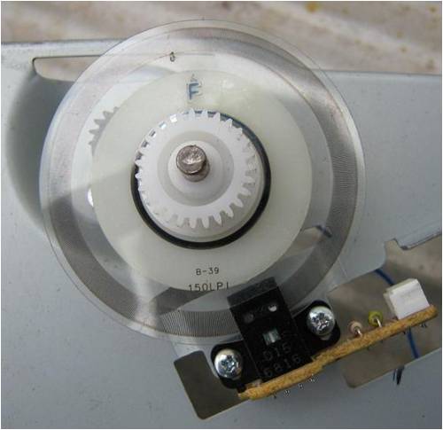
Here you can see the black lines i had mentioned, by the look of the printed text it could be 150 Lines Per Inch 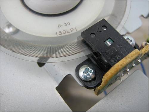
There is several different configurations with the wiring of the boards, here you can see i have marked the 3v+ input with a red mark and ground with a black mark and the other 2 pins in blue are signal out 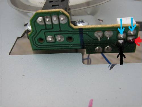
Here is a different board with a different pin configuration, marked as before. 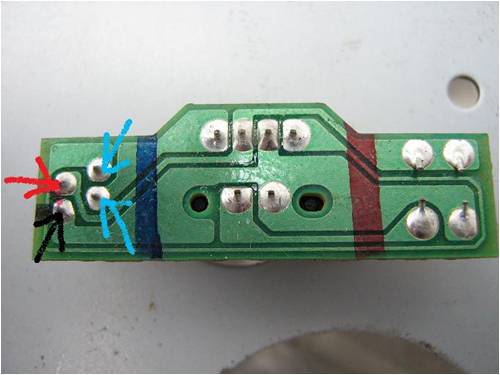
Your board might be different again and is why i ask for a photo. For your interest there will also be a straight plastic strip about a foot long with a photo sensor at the back of the printer carrage that you might have a use for in a different project. (Linear travel) Lots of good little sensors in a bubblejet if you look carefully. 
Pete. Sometimes it just works |
||||
Downwind Guru Joined: 09/09/2009 Location: AustraliaPosts: 2333 |
I fired a sensor up and got some values for you. At 3 volt input they draw around 20mA so will require a 330 ohm dropper resistor for 5 volt operation. The signal out swings between 0 volts and 0.3 volt so you will need to feed it through a Op-amp or a comparator with around a 10 to 1 gain so the picaxe can detect it. If you want to display the data on a lcd and dont wish to use a serial lcd than it might be best to use a 20x2 picaxe instead of a 08m as the 20x2 has enough pins to drive the lcd direct. If you would like to display the data on a computer and even record it on the PC than a 08m picaxe would do fine. ( the 20x2 will also allow for data logging) Ok i have hit you with a few things to consider but dont be frightened off as the electronics are rather easy, and you will have a very good anemometer of high resolution when completed. This will also give you a good foot in the door to be able to log data from the wind and your mills. Once you see how easy it is to record data from wind speed you will find the next step of recording (logging) data from your windmills a easy step to take. If you are happy with a wind speed resolution of 1 to 5 minutes than an anemometer with just 1 target per revolution is fine, but it is almost useless should you wish to log other data in the future as it slows up the logging rate to be almost useless. I sample the wind speed 4 times a second with the printer sensor system. Here is a schematic of the basic system required, this will allow you to record/display the data to a PC and it could be expanded to allow a lcd. Pete. 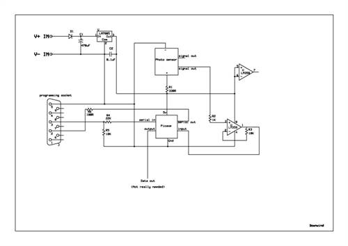
Heres a download PDF or the schematic (much easier to see) 2010-12-20_182539_anemometer.pdf Sometimes it just works |
||||
| GWatPE Senior Member Joined: 01/09/2006 Location: AustraliaPosts: 2127 |
Hi Isaiah, I am all for making your own anemometer, but as Pete has identified, low friction is paramount. Long life of the cups and bearings can also be a problem. As you already have the anemometer hardware, you might want to just reuse it with say a picaxe 08M. I would not use the count command, but use the pulsin command. I have a cup anemometer with a reed switch producing one pulse per revolution. The pulsin command allows an update rate of several readings per second, and produces an update rate that increases linearly with the windspeed. This is quite different to the constant update rate offered with the count command. I get a resolution of 1kph [0.3m/s], without much trouble, with just the 1pulse per rev. I had to use a bit of code to filter the data stream, that can have noise from the reed switch. This is a little subroutine I use on a picaxe 20X2. readwindspeed: setfreq m4 pulsin c.0,1,w20 'test for falling edge if w20>0 then w20=65535/w20 endif pulsin c.0,1,w21 'test for falling edge if w21>0 then w21=65535/w21 endif if w20=w21 and w20<400 then ws=ws+w20 ws=ws/2 endif return This code operates fast enough, but I did find that even though the main program can run at 32MHz, that I still run the pulsin loop at 4MHz. I test for consecutive readings to be the same and ignore really short pulses. The subroutine returns the same windspeed for corrupt data and only updates a rolling average with a successful read. I came from a scientific background, so I like to see formatted numbers, that reflect the precision of a measurement. I don't see how a windspeed of say 35.43kph means much. You will need to decide how much precision you give to displayed data. The resolution of the readings you display should be proportional to the sampling rate. If you sample at 10 readings per second, then a resolution of 0.1kph is on the cards, but if you have 1 reading per second, then you really only need to display in 1kph resolution. The windspeed is quite changeable and rapid in the changes. The resolution of less than 1kph is really only of use below about 5kph, and there is not much wind energy here to worry about measuring or recording it with high resolution. High resolution is only possible with extremely low inertial mass and bearing friction of the measuring cup mechanism. Here is a graph of windspeed at my place measured with the code above. This is a 3min time window, recorded at 1sec intervals. I have recorded data to a resolution of 1kph, but display to a resolution of 2kph. The range is from 6kph to 30kph. Breezes change speed relatively slowly, but wind changes speed quite quickly. [approx 2kph/sec at these relatively low windspeeds] 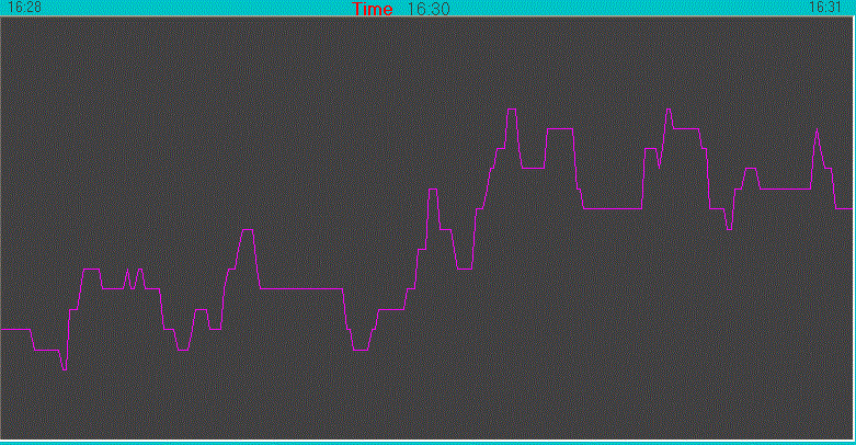
If I was to record at 10 readings/sec, then there would be benefit to have a display resolution of 0.1kph, to show a smmother graph. Measuring windspeed is difficult. Once you get the mechanicals right, you will have to get the calibration right. If you have a resolution of say 0.1kph, you need to calibrate with wind, measured with at least the same accuracy. I have found that measuring to 1kph resolution is about the practical limit, even if spot readings can be made to a higher resolution. Once you get this measurement in hand, a better correlation with other windmill power measurements can certainly be made. Gordon. become more energy aware |
||||
| isaiah Guru Joined: 25/12/2009 Location: United StatesPosts: 303 |
Thank You for the input guys . I took pictures with Bubs camera so they should be up soon. I do have another of these printers as foe a while you could buy a new printer cheaper than you could buy the ink cartages. Buy a new one and throw the old one out. I bought a dell laser printer as they don't dry up the ink like the ink jets do and most of my printing dosen't need color. It looks like Ill have to turn the shaft to fit the bearings for the optical coupler? What did you mount your motor into to keep it weather tight? We may be a bit getting our bits and pieces around for this project. Bub did down load some software for the pickax. Also we only use Linux systems here.No windows URL=http://www.motherearthnews.com/Renewable-Energy/1973-11- 01/The-Plowboy-Interview.aspx>The Plowboy Interview[/URL> |
||||
| Bub73 Senior Member Joined: 10/12/2009 Location: United StatesPosts: 116 |
Hi all I haven't done anything with picaxe before the lack of linux software was the big issue and lack of a serial port also. Today I discovered they do have linux and Mac software so I downloaded it. I'll try to compile and install it in the next day or so also will have to find my old usb to serial adaptor and get it working. I'll try an get isaiah's pics up tonight; the batterys are exhausted on both our camera's after todays photo shoot and are recharging now. Bob |
||||
| Bub73 Senior Member Joined: 10/12/2009 Location: United StatesPosts: 116 |
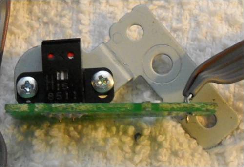
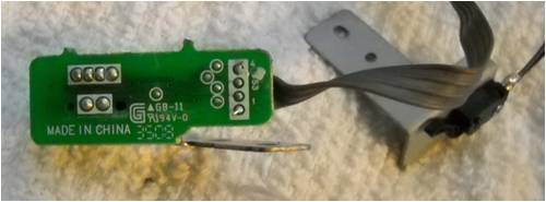
Here is isaiah's photos; they look very close to what Pete posted. Bob 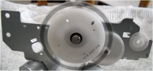
|
||||
Downwind Guru Joined: 09/09/2009 Location: AustraliaPosts: 2333 |
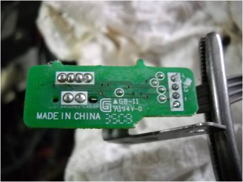
Bugger the tracks are on the other side of the board and my Chinese made crystal ball is broken, and i cant find my xray glasses. You might need to add another photo showing the tracks. Pete. Sometimes it just works |
||||
| isaiah Guru Joined: 25/12/2009 Location: United StatesPosts: 303 |
Bub will have to put it up tomorrow. URL=http://www.motherearthnews.com/Renewable-Energy/1973-11- 01/The-Plowboy-Interview.aspx>The Plowboy Interview[/URL> |
||||
| Bub73 Senior Member Joined: 10/12/2009 Location: United StatesPosts: 116 |
Maybe these will be better... 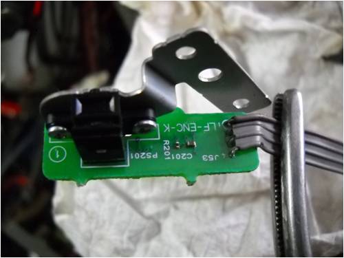
Bob |
||||
| isaiah Guru Joined: 25/12/2009 Location: United StatesPosts: 303 |
Pete, Do you have any pictures of your unit? What did you use for the outside casing and what did you use to fasten your cups to? I did dismantle two old VCR's today and found 1 motor in each that has a double bearing that runs real smooth. Some of the outsides of this motor are 2 1/2 inches,I was thinking of some sort of pvc Pipe to put it in. The outside diameter of this motor is just a bit smaller than the opticoupler. It may work out good but the shafts are different diameter. I was thinking of making like paddles rather than using cups. I'm thinking of cutting something out of pvc pipe and gluing it on to the top (or bottom) of the rotor.There was some other small motors in there a axial flux and small pm motors. and a 120v power supply that Bub will have to see if he can use for something. URL=http://www.motherearthnews.com/Renewable-Energy/1973-11- 01/The-Plowboy-Interview.aspx>The Plowboy Interview[/URL> |
||||
Downwind Guru Joined: 09/09/2009 Location: AustraliaPosts: 2333 |
I did not take a lot of photos of the last anemometer i built but there is a few back in the thread i posted a link to earlier on page 1 for you. The housing was made from a 75mm (3") pvc stormwater pipe cap, with a ring of 90mm stormwater pvc pipe lapping over the cap so as to make a rain proof seal. I cut a disc of plastic (the black bit) and routed 4 cross grooves in it for my 1/8 brass spokes to fit into. I used a little silicon to stick them in and sandwich them between another top plate (in this case it was one of the platters from a Hdd) The cups were Easter egg molds ( a bag of 10 for a $1.00) The bearing assembly was the motor from a computer hard disk drive (Hdd)with the iron core and coil windings removed from the motor. The photo interrupter disc had the plastic centre mount drilled out and cut to shape to fit into the bottom of the Hdd motor where the coils were and it all glued in with silicon. It is very important to get the disc level as if it touches the photo sensor as it spins through the narrow gap it will rub the black lines off the disc and then not work. It is important to keep the weight down to a minimum as this will effect how the anemometer will accelerate and slow in the changing wind. I would not use paddles as the weight will be to heavy out there, one i built earlier used on under arm deodorant caps that was dome shaped. As mine has about a 12" diameter out where the cups are, i used 4 cups as 3 cups and a large dia. they become a little sparse between the cups (3 is ok on a small dia.) Also i was lazy and to cut a cross to locate the spokes was easier than trying to get 3 equal sections. As for old video parts there will be some good motor driver chips on the board too the Bub might find a good use for. I have ratted many over the years for driver chips. 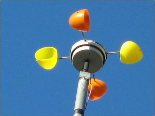
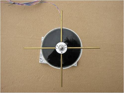
As i said the hard part is building the actual anemometer, the electronics is not so hard. The whole thing is build one and see how it goes as you will then have a good idea on what to do for the second one as it is likely you will end up making more than one as i did. Mine works on a wireless transmitter for sending the data, but as you said there can be issues with using wireless and if you are not into electronics than a wired system if a lot more fool proof. Pete. Sometimes it just works |
||||
Downwind Guru Joined: 09/09/2009 Location: AustraliaPosts: 2333 |
For the wiring of the sensor i think this should be correct from what i can work out. You can use either "SIG" (signal output) as it wont matter in this case. I would solder wires direct onto the spots where i have indicated and bypass any exsisting circuit. Pete. Sometimes it just works |
||||
| isaiah Guru Joined: 25/12/2009 Location: United StatesPosts: 303 |
Well I went in to Home Depot today and a 4'' pvc cap is $7.35 ea. The diameter of the opti disk and sensor I need about 4'' to get it in. So I brought some home.I also got some 2 inch and 1 1/2 inch pvc caps to try for the wind cups if they aren't too heavy. Now I have to figure how to fasten this stuff inside the pipe cap. And We have to know where we can find a transmitter to make this wireless and a leanyer amplifier to make sure the signal get to the house!! URL=http://www.motherearthnews.com/Renewable-Energy/1973-11- 01/The-Plowboy-Interview.aspx>The Plowboy Interview[/URL> |
||||
Downwind Guru Joined: 09/09/2009 Location: AustraliaPosts: 2333 |
What is the distance you need to transmit. What type of building do you need to transmit through. (brick, sticks, straw  oink, oink.) oink, oink.)
Pete. Sometimes it just works |
||||
| Page 1 of 3 |
|||||