
|

|
Forum Index : Other Stuff : NextG Yagi aerial.
| Page 1 of 2 |
|||||
| Author | Message | ||||
| Gizmo Admin Group Joined: 05/06/2004 Location: AustraliaPosts: 5078 |
This might be a bit of handy info for anyone who like me uses a NextG modem for their internet access. I cant get ISDN or ADSL, Satellite is too expensive, so its NextG wireless for me. My NextG modem/router ( Bigpond 7.2 Home Network Gateway ) came with a little 3 inch aerial that screwed into the back of the router. Actually there are 3 aerials, one is the primary aerial, one as a axillary, and one for WiFi networking. Its also got 4 lan ports, not a bad bit of gear really, works great. I'm about 30km from town and with the little aerial I was on 3 bars signal level, about half. The NextG network internet bandwidth depends on signal level, so better signal = better download speed. With this in mind I bought a high gain dipole "whip" aerial for $150. That improved the signal level to 4 bars, and there was a good improvement in internet speed. Its been clamped to a chair on my front patio for the last few years. I did have it on the roof but I was tired of unplugging it every time there was a electric storm in the area. 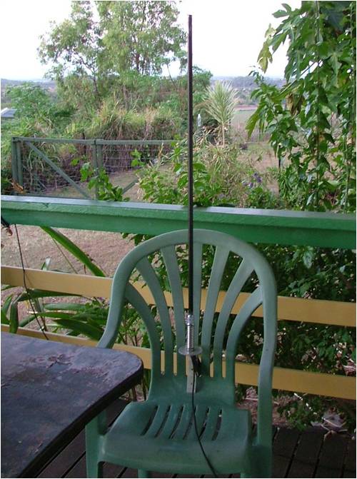
I was pretty happy with it, but a few days ago I stumbled across a web site where a amateur radio hobbyist built a yagi aerial for his NextG phone for when he goes camping. This is the page I found... http://www.perite.com/vk7jj/nextgyagi.html I bought some 50ohm low loss coax, connector and a length of 10mm aluminum tube. I already had the PVC pipe. All up I spend about $50. I bought double the coax I needed, the girl behind the counter was cute and I forgot how much I needed  . This is the result. . This is the result.
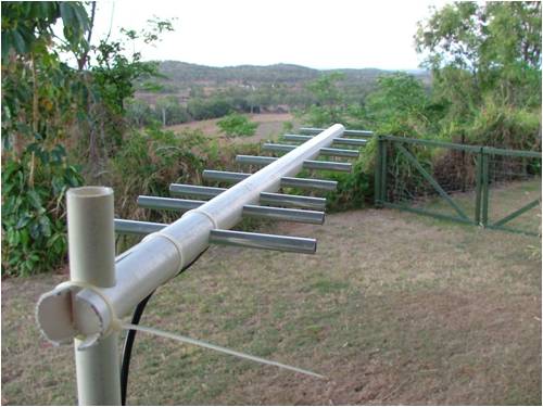
With the new yagi connected up, I get full signal strength, 5 bars  . A speed test to Brisbane gave a ping of 167mS, a download speed of 1.44Mb/S and a upload speed of 0.84Mb/S. Thats pretty darn good! . A speed test to Brisbane gave a ping of 167mS, a download speed of 1.44Mb/S and a upload speed of 0.84Mb/S. Thats pretty darn good!
Glenn The best time to plant a tree was twenty years ago, the second best time is right now. JAQ |
||||
| Dinges Senior Member Joined: 04/01/2008 Location: AlbaniaPosts: 510 |
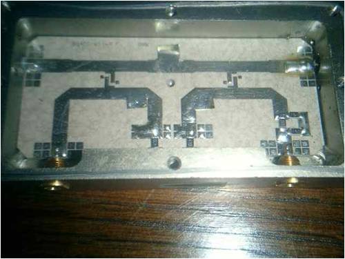
13.5 dBi gain? Not too bad.... I never got good results at those frequencies with DIY Yagi antennas, good to see you did. I notice the elements have very large diameter (compared to what I used in the past for some 1296 MHz antennas I've built). This explains the wide bandwidth (wide frequency range) of course. If you ever have the chance, take the antenna to a HAM antenna measurement fest to get it properly measured for gain, front-back ratio, bandwidth, and to determine the true gain pattern. At least, I like to know these things of my antennas. Then again, if you're happy with the results of it, why bother. Not sure how far your enthusiasm w.r.t. the black magic of antennas goes. What I prefer at those frequencies over Yagis though are double-quads (easy to make, and tunable for optimum SWR if you build it correctly; the results are *very* sensitive w.r.t. distance from the element to the backplane. http://www.frars.org.uk/cgi-bin/render.pl?pageid=1064 ) or of course the parabolic reflector, though at 900 MHz it'd have to be still relatively large to get enough gain. If you want to I can get you a little something with which you easily can build your own SWR bridge for antenna measurements - it'd help in tuning the antenna for optimum performance. The bridges I have (ex-telecom) were used in 900 MHz cell stations (0.1 dB insertion loss), but are usable up to 1300 MHz. Let me know if you want one - proper teflon print with stripline loops. Add a little meter and a potmeter and you can make accurate SWR measurements at those frequencies. Let me know if you're interested and will send two your way - no charge of course. 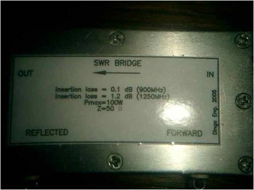

At those frequencies, the coax you use makes a lot of difference too; I see you've used low-loss coax. Good idea - would be a shame to waste those preciously gained dB's of gain in cable losses. Also, if you have or know someone with some RF attenuators, you could try to determine how much loss you must introduce in the system before you're back down to your 3 bars signal strength - that would help in estimating how much extra gain your new antenna *really* gives (in my experience, results from an antenna calculator and real-life results often differ...) Building antennas is easy (mechanically simple), fun and cheap, and can yield excellent results. But there's also a lot of black magic involved. Good to see you got good results - not trivial at those frequencies. Peter. Edit: once had the privilege of playing around with a 7.5m parabolic antenna (ex-WW2 German radar: http://en.wikipedia.org/wiki/W%C3%BCrzburg_radar)for solar noise measurements; I can't help but wonder how many bars of signal strength you could get with one of those....)  |
||||
| Tinker Guru Joined: 07/11/2007 Location: AustraliaPosts: 1904 |
Thanks Glenn, you did not post this info in vain  . .
While I have not yet got a nextG wireless link it was on my mind to get one for the time the laptop is on the road. This antenna looks just the ticket and, since all the parts are already lurking in my shed somewhere, its a great excuse for another project. I think you made it harder (to connect it) by using a tubular boom, I think I'll try the PVC channel conduit as shown in the article, with the lid popped back on it should be rigid enough. I too have noticed that Bryan's foot is often hovering too close to the 'rant' pedal, a pity since he seems to be a nice guy who has in the past given me valuable info that saved me a lot of money. Maybe living out of town does have its drawbacks with limited choices on essential services. Klaus |
||||
| philb Regular Member Joined: 05/07/2008 Location: United StatesPosts: 96 |
Glen, A few months ago, I bought an AT&T Mercury dongle. I live out from town and the nearest tower is ~20 km away. Two towers are actually in sight. My remedy was a Wilson antenna made for truckers. It normally gives me 3 bars and 3G on occasion. That's not too bad when there were no bars before. The entire setup was about $100usd. The signal is still unsteady. Transition from non 3G to 3G appearantly means a disconnect and reestablishment of the signal. If I don't use AT&T's software, it causes me to have to manually repair the connection in Windows. I have been looking for an affordable Yagi and could not find one. I'll bet I have enough junk antennas parts to put this one together this weekend. How are you attaching the driven elements inside a round tube? [on /rant] I do appreciate the posts on this site. I do enjoy it. It is useful. Glen, it is worth the bother. [off /rant] philb |
||||
MacGyver Guru Joined: 12/05/2009 Location: United StatesPosts: 1329 |
Gizmo & Crew: I don't know diddly about electronics OR Australia, but here in the states, there's a Starbucks Coffee shop on every corner. There are also many other venues that offer FREE Internet hookups that are NOT password protected. I said all that to say this: Here's a link: http://prospecting.50webs.com/wifi.html Posting active links for me is like pulling teeth--just copy and paste! At any rate, this is a yagi antenna that sells for about $125 US and will pick up Wi-Fi signals line of sight for about 10 miles. All you do is aim it towards a city and it apparently does the rest. I don't have one yet, because the guy selling them said they don't like Macs; they'll work, but its a real chore to install. Apparently the software is written for a PC and something is lost in the emulation translation. Maybe this would work for the Australia crew too -- if anyone is near a town with a free Wi-Fi venue. Check out the link; I'm hoping maybe it'll work for someone. Nothing difficult is ever easy! Perhaps better stated in the words of Morgan Freeman, "Where there is no struggle, there is no progress!" Copeville, Texas |
||||
| davef Guru Joined: 14/05/2006 Location: New ZealandPosts: 499 |
Dinges, Looks like you (or someone) put in quite a bit of work optimising the directivity of those forward and reverse couplers! Do you what the measured directivity is? davef |
||||
| Dinges Senior Member Joined: 04/01/2008 Location: AlbaniaPosts: 510 |
Dave, I don't know more measured results than what I put on the label - long story... :( I spent about an evening measuring it in any possible way with a friend who had borrowed a networkanalyzer from his work for the evening. I made only very few notes myself that evening, as the analyzer had storage capacity and could print very sexy graphs when hooked up to a PC. When the analyzer was returned to his work, another colleague used it and removed all data. ARGH! An entire evening gone to waste. All I know now about it is the insertion loss at those two frequencies. What I do recall was that it performed generally very well in all respects up to 1000 MHz, and very usable up to 1300 MHz (23cm band). The optimizing was done by the original manufacturer by adding bits of foil, scraping away pads, making cuts, etc.etc. They didn't spare time or effort trying to get the best results out of it. Another reason why I generally love ex-telecom stuff.... built to high standards. Just checked - that 7.5m Würzburg-Riese antenna should yield about 35dB gain at 900 MHz.... Peter. |
||||
| Gizmo Admin Group Joined: 05/06/2004 Location: AustraliaPosts: 5078 |
Thanks for the feedback guys. I deleted the nasty posts, both mine and someone elses, I was having a bad day and easily pushed too far. Yes its proving to be a good aerial. I didn't have any square or rectangle conduit unfortunately, so used the round 20mm PVC pipe instead. I was thinking of using some timber, but then I would have to waterproof it. Drilling inline holes on round stock is a pain, but its all I had and it ended up OK. I followed the measurements as close as I could, I'm confident its all within .25mm. I started my apprenticship as a radio technician, and it was fun to dabble in aerials again after so many years. I have a couple of satelite dishes just begging to be experimented with WiFi. I might take you up on your offer Dinges, just one would do, I'll send you an email over the weekend. It would make a useful SWR meter for setting up wireless and NextG. I do have a SWR meter for setting up CB and VHF stuff, but nothing this high in frequency. Glenn The best time to plant a tree was twenty years ago, the second best time is right now. JAQ |
||||
| greendreamin Newbie Joined: 02/02/2008 Location: AustraliaPosts: 20 |
thanks fellas working on moovin out of the city in the next few years and been wondering about a decent speeed internet connection will keep this in mind Stu  |
||||
| Gizmo Admin Group Joined: 05/06/2004 Location: AustraliaPosts: 5078 |
Here's how I attached the coax to the driven elements. I used crimp connectors, soldered as well. Kept the exposed inner as short as possible, and the screw terminals as close to the inside ends of the driven elements as I could. 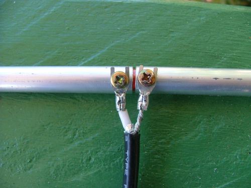
Underneath the PVC tube I had drilled a 12mm access hole. The way it worked is I slid in the driven elements from one side untill I can see the screw holes, and screwed down one terminal, then slide a bit further and screwed down the other terminal. The holes in the PVC were a neat fit around the 10mm aluminium tube, loose enough to slide the aluminium pape through with a little pressure, and tight enough that I dont need any glue. Yes, it was a fiddly job, like building a boat in a bottle, and I wished I had used a wood beam instead of trying to be smart and using PVC pipe cause it looked better. But it did go together eventually. 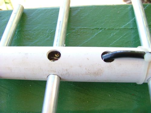
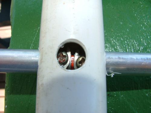
Glenn The best time to plant a tree was twenty years ago, the second best time is right now. JAQ |
||||
| Tinker Guru Joined: 07/11/2007 Location: AustraliaPosts: 1904 |
Thanks for that Glenn, now I know there's another chap on this board who likes a challenge  . .
I would have used solder eyelets under the screws, they are even smaller and perhaps more secure than the crimp spade terminals. I wonder why you choose to run the coax through another hole, why not run it past the reflector tube and out of the end of the PVC tube? Edit: looking at your initial pics again I see why, you have the mounting pole at the end of the boom! Klaus |
||||
| davef Guru Joined: 14/05/2006 Location: New ZealandPosts: 499 |
As well as mm accuracy on the elements, the boom material and diameter are very important. I would be very surprised that the feed impedance on a long Yagi was anywhere near the 75Ohm (?) cable you are using. The distance between the two halves of the dipole will effect resonant frequency as well as the material used to hold them in position. Matching and baluns are the next topics to consider. Where did you get the dimensions? |
||||
| Gizmo Admin Group Joined: 05/06/2004 Location: AustraliaPosts: 5078 |
Hi Dave Its 50ohm low loss cable. On the cable is says CELLFOIL LOW LOSS RG58 TYPE RFI CAT. NO.9006 All the lengths and spacing between the two halves were measured with my trusty old verniers. The dimentions are in the link in the first post. Glenn The best time to plant a tree was twenty years ago, the second best time is right now. JAQ |
||||
| davef Guru Joined: 14/05/2006 Location: New ZealandPosts: 499 |
OK on the coax. I saw the ally foil and thought it might be low-loss TV coax. Interesting design. Does that plastic strip that separates the dipole elements also separate the directors or do the directors just go through that strip? 50 Ohm direct feed, I'll have to brush up on the technique. The first director does look close to the driven element, which might help to raise the dipole impedance. From my reading, the feed impedance of long "gain-optimised" Yagis are "quite a bit lower" than 50 Ohms. However 13dBi is not too bad! Still not sure about not using a balun. Do you notice a skewed directional response or signal variations from running your hand along the coax, say up to the back end of the boom? BTW, thanks for putting the article on about oven elements. Cheers, Dave |
||||
| davef Guru Joined: 14/05/2006 Location: New ZealandPosts: 499 |
58MHz (at 880MHz) for 1.5:1, that is impressive for a long Yagi. Have to have a closer look at what the antenna gain is like at 838MHz, as he shows the gain at 880MHz. Just finished building a Cantenna for 2.1GHz mobile broadband. Used a Bruichladdich Islay single malt whiskey container. Got a 20dB match from 1.9GHz up to about 2.3GHz. That only cost me an N connector, as the container came free  |
||||
| Dinges Senior Member Joined: 04/01/2008 Location: AlbaniaPosts: 510 |
"Its 50ohm low loss cable. On the cable is says CELLFOIL LOW LOSS RG58 TYPE RFI CAT. NO.9006" Glenn... not nitpicking... but 'RG58' and 'low loss' are not words I ever expected to see in the same sentence  . .
Never mind - it works. And 900 MHz is still doable with RG58, as long as your cable run is limited. And I'll admit - RG58 works much nicer than RG8 or other thick, low-loss coax. Come to think of it, I'm using RG58 on 2.3GHz as well.... Dave: I've got very good results with cantennas too. Easy to build as well. Yagis never worked for me at those high frequencies, the highest frequency I got one to work was 70cm - took a lot of experimenting and tuning, but the results were amazing (accessing LEO satellites with a handy on .5W) Using 50 ohm (asymmetric) coax on a 75 ohm (symmetric) antenna is not too much a problem; there will be slight extra losses due to it though; depending on the design of the yagi, the driven element may even be close to 50 ohm? The symmetry is another thing though. It'd probably be a good idea to make a 'choke' by coiling 5-6 turns of coax close to the antenna? Peter. |
||||
| herbnz Senior Member Joined: 18/02/2007 Location: New ZealandPosts: 258 |
Hi Very interested in this thread. All my communication is via cellphone system. The latest update is Vodafone's 3G operating here at 900Mhz . Question I have is what mods would be needed to Glens Yagi to work at this ? Also notice the photo shows it horizontal I think we are vertical polarisation. I do have an old yagi here that was used on the old analogue system at 850mhz, sort works but I find a small whip areial designed for 900 better.(internet & phone ) Also I have picked up on our Trademe a active boaster that I try to re transmit on so both phones and internet can be used in blank spots on my property but i assume feedback, creates all sort strange effects . Not my field of expertise here Dave Feed me some more info on cantennas my as well play with these to. Herb |
||||
| Robb Senior Member Joined: 01/08/2007 Location: AustraliaPosts: 221 |
Do you get any noticeable signal difference if you turn it vertically polarized? I would have thought it should be vertical being a system thats designed to work with omni directional mobile antennas at the customer end. |
||||
| Gizmo Admin Group Joined: 05/06/2004 Location: AustraliaPosts: 5078 |
Hi Herbnz Mate I would only be guessing at the changes needed to run at 900MHz. At these frequencies the element lenghts and spacing is critical. If you follow the link in the original post, the author mentions some software he used to design the yagi. I did do a search, found the software and installed it, but it got to complicated after that for me, its been a long long time since my radio training. The software is good, the answer is in there if you've got a few free hours. Hi Robb Good question, I just tried that to see. Horizontal mounting, as show, gave a -58dBm signal level, which the router calls "High". Vertical mounting droped to -79dBm, or "Medium". Needles to say, I changed it back to horizontal mounting. Glenn The best time to plant a tree was twenty years ago, the second best time is right now. JAQ |
||||
wallablack Senior Member Joined: 10/08/2011 Location: AustraliaPosts: 164 |
Stumbled across this doing a Google Image search for Yagi's. I am just about to build one myself as our internet reception here is woeful. We have a tower on the hill behind us but the signal shoots straight over our place. Thanks for posting this one. Foolproof systems do not take into account the ingenuity of fools. |
||||
| Page 1 of 2 |
|||||