ChargedUp
Newbie

Joined: 23/12/2012
Location: United StatesPosts: 4 |
| Posted: 08:18am 17 Feb 2013 |
 Copy link to clipboard Copy link to clipboard |
 Print this post |
|
have been talking to a lot of people about setting up their charge controllers and inverters for use with Nickel Iron batteries.
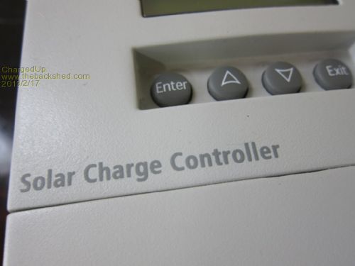
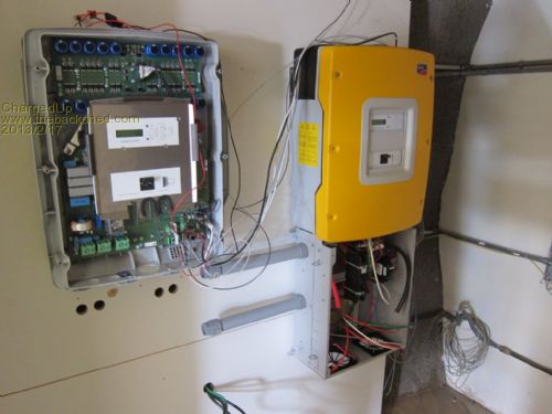
Most recently, I was working on a Xantrex XW 6048 system with a 400Ah 48V Ni-Fe battery. There was one XW60 charge controller, the 6000 Watt 48Volt inverter, and a System Control Panel.
This system was previously configured to use lead acid batteries, so the charger was set to bulk up to 54 Volts. With the Nickel Iron battery, we need to charge up to a higher voltage. I took detailed notes while configuring the system to work with the new battery, and the setpoints we changed are shared below.
In general, we want each cell to charge at 1.6 Volts or higher. Ideally, we would like to get each cell up to 1.65 - 1.67 Volts per cell. Now is a good time to grab your calculator...
1.2 = nominal Voltage of a Ni-Fe cell
1.2 Volts x 40 cells in series = 48 Volt battery
1.45 = Voltage per cell when full, at rest, not charging or discharging
1.45 Volts x 40 cells = 58 Volts This is already higher than the 54V set point for the lead acid battery.
1.65 = Voltage we want to hold for full charge
1.65 V x 40 cells = 66 Volts For many inverters, this is higher than the HBCO (high battery cut out)
At this point, we change the configuration of the battery to run with 38 cells instead of 40 cells.
1.2 x 38 cells = 45.6 Volt nominal capacity. The SMA Sunny Island inverters actually default to this nominal voltage when you select Nickel-type battery in the setup menu.
1.45 x 38 cells = 55.1 Volts The normal operating range for this battery is 55.1V - 45.6 Volts. The LBCO (low battery cut out) for most inverters is down at 40 Volts, although the old trace Trace can run down to a super-low 36 Volts. At 40 Volts, with 38 cells, each cell is working at 1.05 Volts. The very low point for a Ni-Fe cell is 1.0 Volts, so we are only 5 one-hundredths of a volt away from terminal voltage.
1.65 x 38 cells = 62.7 Volts This voltage is well below the 64V HBCO (high battery cut out) for most inverters. The key here is that we can set the charge controller and inverter / charger set points a little higher and achieve a near constant current charge algorithm, no matter what kind of equipment we are using. When the charge controller or inverter has to work all day to get up to the max charge voltage, it is delivering max current in the Bulk charge cycle. We are basically telling the equipment to achieve a battery voltage that is unattainable, which keeps the chargers working at max output as they do their best to get the battery up to that level.
Some inverters like Outback allow you to set the Absorb exit amps, which means that even if the charge cycle were to go from Bulk to Absorb, the amps do not taper to 0. Rather, the Absorb exit amps setpoint allows us to deliver 80% of the charger output at the very end of the absorb cycle. When we set the Max Absorb Time to 5 hours or more, we can lengthen the time it takes to taper the current from 100% to 80%. Remember that we would likely have spent most of the day in Bulk, and only a fraction of the actual charge time in Absorb. The point here is that we can configure nearly any piece of equipment to work with a 24V or 48V Nickel Iron battery.
Please let me know if you have any questions, I am happy to help!


|

