
|

|
Forum Index : Other Stuff : AC three Phase Question?
| Author | Message | ||||
| WindyMiller Regular Member Joined: 05/04/2011 Location: United StatesPosts: 62 |
WARNING HIGH VOLTAGE DIRECT CURRENT. DANGER Gidday, I have a few questions I was hoping someone could please answer? What I have is a small generator I built that can supply HV DC and AC. This generator is a standard delco remy 63 Amp 10 SI setup to supply 110 Volts DC. The DC side works perfectly and has been fully operational for two and half years now. The setup is based on information contained in “ Alternator Secrets”, this little book was available from Lindsey Publications a few years ago. The setup uses a 4 pole double throw switch. This switch disconnects the V reg, routes the B+ stud to a standard household receptacle, and supplies full 12 volts to the rotor field. My stator is connected in a Y configuration so what I did was tap all three phases off the diode studs. I connected two receptacles across two of the phases and used the third for a common return for both outlets. When I have the right engine speed for the DC to be at 110 volts I am seeing 70 volts at the AC plug, However there is no amperage? A standard 100 watt light bulb barely lights at all. My setup right now is just like the following drawing. Drawing 1: 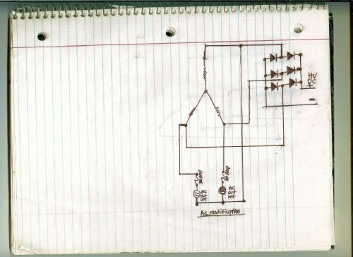
So my question is this: Can I connect the Y point to the negative side of the rectifier bridge without blowing my diodes to kingdom come like drawing two? If so then I could use the Y point and have three separate loads connected across the three phases and the return to the case. I was also told that grounding the Y point would improve efficiency somewhat of the alternator overall Drawing 2: 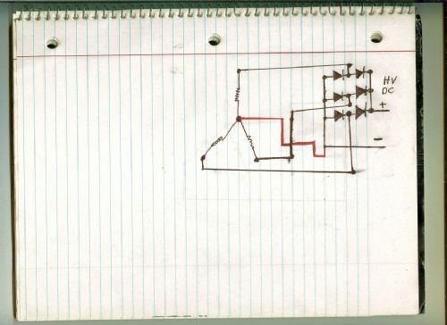
If this would indeed work without ill effects to my diodes then drawing 2a would be possible? Drawing 2A: 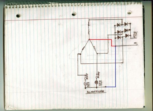
If this setup will not work without ill effects to the rectifiers would any of the following be the proper connection methods? Drawing 3: The use of two additional diodes for the Y point connection. The problem I have with this setup is the fact there is no space inside the alternator and I am trying hard to keep everything self contained without outside heat sinks and diodes, etc. If this is the correct method what kind of diodes should I use? 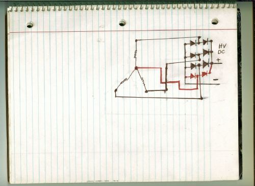
Drawing 4: I have been informed there could be a 27 volt difference at the Y point. For this reason it was suggested I use a Neutral grounding resistor for the connection to the diode bridge negative stud. If this is so? What size resistor should I seek? This would be the easiest method for my setup as a resistor is small and would fit in the tight space I have inside this little alternator. I have 89 1.6 Meg Ohm 250 Volt resistors left from wiring a DC volt meter. Would these work for this connection? I would love to find a use for these as they are just sitting in a bin right now. 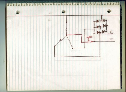
Drawing 5: Drawing 5 is a single diode soldered into a very short piece of wire from the Y point to the negative side of the diode bridge. Would a 1000 Volt 1/2 Amp diode work for this connection? I got 4 of these on hand in a junk box right now. 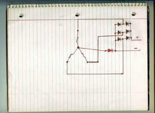
What the goal is right now is this: I am hoping to get at least 60 volts AC with some amps. If I can get that far then I can use a set of transformers to step up the voltage to 110 if I have to. This is the setup for the transformers I have in mind. 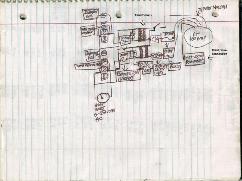
The capacitors in line from the alternator is because someone told me there is a lot of DC in the windings coming from the diode bridge. If this is the case the caps are to stop the DC, but let the AC pass to the transformers. Is this way of thinking sound? Sounds correct in theory to me anyway. The caps in line from the alternator to the trannies are 0.86 UF at 2100 volts. The filter caps across the outputs of the transformers are 0.76 UF at 2100 volts. I know the drawing is hard to read so if anyone has questions just ask? Robert |
||||
| Warpspeed Guru Joined: 09/08/2007 Location: AustraliaPosts: 4406 |
Drawing 1 is the only one that will work. A typical car alternator will generate around 14 volts at 2,000 rpm, and 140 volts at 20,000 rpm. Open circuit with no load. That is not an exact measurement, just very roughly about what to expect WITH FULL field excitation. And that voltage will fall as soon as you place any load at all on it. To get any significant power at 110 volts will need a very high drive speed, plus a lot of horsepower to turn it. Automotive alternators have very low efficiency, they have very little copper and iron inside. They are made to be small and light weight (and cheap) for the high power they can produce. When you have a huge powerful car engine driving it, none of that matters. For homemade power, they leave a lot to be desired, which is why very few people use them. Cheers, Tony. |
||||
| WindyMiller Regular Member Joined: 05/04/2011 Location: United StatesPosts: 62 |
Tony, I chatted with a transformer winder locally who said that if the y point was brought out of the case that three loads could be attached across the three phases with the neutral return to the y point. Would that work or just cause problems as well? Edit: Looks like this alternator uses a common neutral to the y point? Link Robert |
||||
| Warpspeed Guru Joined: 09/08/2007 Location: AustraliaPosts: 4406 |
That would definitely work. The transformer ratio will pretty much determine the voltage versus rpm relationship, so the alternator can then turn much slower to generate 110 volts. The operating frequency will not be 60Hz, but very much higher, and the transformers need to be designed with that in mind if transformer core eddy current overheating is to be avoided. Overall power efficiency will still be quite low, and the voltage will still fall under load. But not by quite as much. Cheers, Tony. |
||||
| WindyMiller Regular Member Joined: 05/04/2011 Location: United StatesPosts: 62 |
Tony, If that works then why would grounding the diode bridge to the y point neutral cause problems? Robert |
||||
| Warpspeed Guru Joined: 09/08/2007 Location: AustraliaPosts: 4406 |
Connecting a transformer from phase to phase is very different to shorting out windings with diodes. Cheers, Tony. |
||||
| WindyMiller Regular Member Joined: 05/04/2011 Location: United StatesPosts: 62 |
This is the idea for the transformer winding. LinkLink2 Ok, Would the way I have my very last drawing work? Or would the filter caps be a buggerment as well? In that drawing two transformers are used. 1 to a phase with the y point neutral connection. Robert |
||||
| Warpspeed Guru Joined: 09/08/2007 Location: AustraliaPosts: 4406 |
Microwave transformer is totally unsuitable. I can neither read or understand your last drawing. Cheers, Tony. |
||||
| WindyMiller Regular Member Joined: 05/04/2011 Location: United StatesPosts: 62 |
The drawing is wired like this. All three phase taps are brought out of the case along with the neutral y point. Two phases are being used for this drawing. The third is not used at present. The phase is connected to a fuse then a series cap before the transformer, The transformer neutral is connected via a switch to the alternator y point neutral. The other side of the transformer is wired to a parallel cap for filtering. then on to the outlets after passing through a fuse. Why would winding a 60 volt primary on a microwave transformer and reusing the 120 volt primary as the secondary not work? According to the transformer winder this would work fine? What sort of transformer would work then? Robert |
||||
| Warpspeed Guru Joined: 09/08/2007 Location: AustraliaPosts: 4406 |
Microwave transformer is a very special purpose CONSTANT CURRENT transformer with a shunt magnetic air gap. You can dead short the 2,500 volt secondary winding, and it will not blow a mains fuse. Welding and neon sign transformers work the same. Ideal for the intended purpose, totally useless as a general purpose transformer. All microwave transformer are intermittently rated, and will quickly burn up if run continuously. I seriously suggest you find yourself another transformer winder. Cheers, Tony. |
||||
| WindyMiller Regular Member Joined: 05/04/2011 Location: United StatesPosts: 62 |
Hmm, Winders are rare in my area so I will have to think on that one for a while? So the tranny would burn up then? What if the steel shunts are pounded out and a wood spacer is made to seperate the winding sets? The higher frequency should allow for the use of smaller transformer correct? Robert |
||||
| Warpspeed Guru Joined: 09/08/2007 Location: AustraliaPosts: 4406 |
Yes you can remove the shunts, but it can be tricky, as the transformer varnish sets like epoxy, and goes as hard as hell once cured. And getting the shunts out without damaging the windings is not easy. Transformer will still very quickly overheat, even under no load. Current density in the wire, and flux density in the core are EXTREME. These are made to run at very high power levels for very short periods from stone cold, then turned completely off for long cool down periods. Totally unsuitable for any kind of reliable continuous operation. Cheers, Tony. |
||||
| WindyMiller Regular Member Joined: 05/04/2011 Location: United StatesPosts: 62 |
So even if rewound with the heaviest wire possible for both windings the lack of steel would still cause them to pop then? The transformer I got was easy to get the shunts out. Just needed a hammer and a square steel rod. Thank heavens no damage to the primary was done either. Robert |
||||
| Warpspeed Guru Joined: 09/08/2007 Location: AustraliaPosts: 4406 |
You cannot increase the wire size without decreasing the number of turns. You can only thread so much copper through a given sized hole. Turns cannot be decreased because the flux density is already dangerously high. Forget it. I cannot conceive a worse or more horrible combination than a automotive alternator coupled to a microwave oven transformer. Spend the money and use proper stuff. Being a cheapskate is just a futile waste of time. Cheers, Tony. |
||||