Notice. New forum software under development. It's going to miss a few functions and look a bit ugly for a while, but I'm working on it full time now as the old forum was too unstable. Couple days, all good. If you notice any issues, please contact me.
Dev7 Newbie Joined: 15/10/2025 Location: South AfricaPosts: 8
Posted: 08:17am 18 Jul 2026
Copy link to clipboard
Print this post
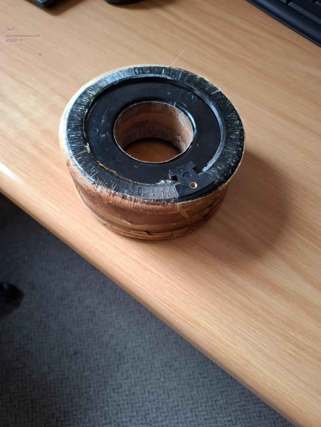
Hi all, I am currently designing a 1kVA 24V to 230V low frequency inverter. I have managed to pick up two faulty 1kVA Variacs that both use a toroidal autotransformer with a variable brush to adjust the voltage from 0-250V. I have unwound one of the transformers so that it is just the bare toroid now.
I want to know if it would be possible to rewind the toroid into a 14V:230V 1kVA isolation transformer that I could use in my inverter design? Pictures uploaded below.
Godoh Guru Joined: 26/09/2020 Location: AustraliaPosts: 705
Posted: 08:55am 18 Jul 2026
Copy link to clipboard
Print this post
HI Dev, it should work fine. Plenty of folk here have used second hand torroids to make their inverters. Most are much bigger than 1kva. I have made a couple for my off grid system that are 24 volt 4kva. I used two torroid cores and stacked them and glued them together. The bigger the core is the less turns you need to use. There are torroid calculators on the web that are pretty good. I have used aliexpress boards for the ones I built, others here have designed their own boards, I suggest that it is good to leave some headroom for regulation under load, i generally wind my transformers for 13 to 250 volts, that way they seem to behave well under load. good luck Pete
Godoh Guru Joined: 26/09/2020 Location: AustraliaPosts: 705
Posted: 08:57am 18 Jul 2026
Copy link to clipboard
Print this post
Oh I forgot to say we wind the transformers for a flux density of 1 Tesla. That seems to work well Pete
disco4now Guru Joined: 18/12/2014 Location: AustraliaPosts: 1151
Posted: 10:06am 18 Jul 2026
Copy link to clipboard
Print this post
See this post for a calculator to work out how many turns required to get 1 tesla. You need to workout the cross section of your toroid in cm and then adjust the number of turns until you get around 10,000 gauss. Note: 1 Tesla=10,000 gauss Frequency is in MHz so 50Hz is .00005F4H7FotSF4xGT
Dev7 Newbie Joined: 15/10/2025 Location: South AfricaPosts: 8
Posted: 03:55pm 19 Jul 2026
Copy link to clipboard
Print this post
Thanks guys, very helpful. I made some core measurements and used the calculator to get the following:
OD = 135mm ID = 60mm Height = 55mm Cross sectional area = 20.6cm^2 230V winding = 500 turns 12V winding = 26 turns
I am slightly concerned, because these core measurements seem too small for a 1kVA transformer. The datasheets of the transformers that are being sold online have diameters and heights slightly larger than this. If I have to, I could probably stack my two identical cores for one very tall core. I am also most likely going to check in with a rewinding shop during the week to see if I can get a quote and get their opinions.
Godoh Guru Joined: 26/09/2020 Location: AustraliaPosts: 705
Posted: 09:55pm 19 Jul 2026
Copy link to clipboard
Print this post
Hi Dev, I would stack the cores if I were you, that gives you much more headroom and also it is a lot less stress on the transformer and it will run cooler. Winding the cores is easy, but takes time. If you stack the cores then the turns will reduce too which makes the job easier. I used a piece of 32mm conduit and bent it into a hoop to load the wire onto to wind my cores. From memory I had about 220 turns on the high voltage side of my transformers.
As your inverter will only be around 1kw then the cable for the low voltage side won't be as big so a 60mm hole in the centre should work. Most here aim for around 90mm centre to fit the big wire for the low voltage side. I ended up using flat glass insulated bar that was for rotor winding on my transformer. It was about 30mm wide and 3mm thick. It worked well but then I only had about 13 turns.
Getting a winding shop to wind the cores could be expensive, but check them out. The wire is pretty expensive too, many folk unwind their cores carefully and re use the high voltage winding wire. For low voltage wire either welding wire or battery cable work pretty well.
good luck Pete
Dev7 Newbie Joined: 15/10/2025 Location: South AfricaPosts: 8
Posted: 02:06pm 25 Jul 2026
Copy link to clipboard
Print this post
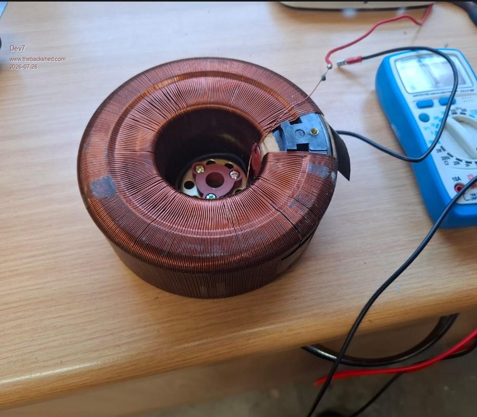
Because copper is so expensive I have decided to keep the existing 250V winding on my other core and go from there. Only problem is that I don't know exactly how many turns were made by the manufacturer to get to 250V.
Before using insulation tape to separate the secondary from the primary could I wind a 'test' primary (using insulated cable) to see how many turns I should be needing? I have 10m of 16mm^2 welding cable that I am aiming to use for the real primary.
I also need some guidance on the 'lightbulb test'. From what I understand, we use a series lightbulb to limit the inrush current while testing. Would I need to do this for a toroid of this size? Thanks.
Edited 2026-07-26 00:12 by Dev7
mab1 Senior Member Joined: 10/02/2015 Location: United KingdomPosts: 286
Posted: 02:29pm 25 Jul 2026
Copy link to clipboard
Print this post
Yes you can wind a test 'primary' to measure the turns/volt: you don't need heavy wire for this as you're just measuring the voltage, whilst powering the 'secondary' from 240v - any handy piece of insulated wire will do, just put, say, 10 turns on, measure input and output volts, and then the maths is easy.
You probably don't need to use a lightbulb: the lightbulb limits inrush which can trip breakers / overcurrent limits on off grid inverters when testing a big torroid. It also indicates if there's a short in the transformer by staying bright; without the lightbulb a short will mean the transformer keeps pulling a lot of amps until something fails/disconnects, which could be a bit dramatic even with a 1kva transformer. It's up to you. Edited 2026-07-26 00:30 by mab1
Godoh Guru Joined: 26/09/2020 Location: AustraliaPosts: 705
Posted: 09:43pm 25 Jul 2026
Copy link to clipboard
Print this post
Mab has answered the questions well. I have used a light bulb (240 volt 60 watt) in series with inverters when testing them after repair. It helps to make sure that the inverter won't destroy all the mosfets if you have missed a component that needs replacing.
In your case testing the transformer to get the right number of turns on the low voltage winding, as mab says it may not be necessary. But it may help stop the circuit breakers on the 230 volt side tripping. Just connect a 60 watt bulb in series with the high voltage winding and you should be fine. Pete
phil99 Guru Joined: 11/02/2018 Location: AustraliaPosts: 3381
Posted: 09:44pm 25 Jul 2026
Copy link to clipboard
Print this post
For the mains test connect the 220V supply between the 0V end and the 250V end of the winding. Leave the 220V tap open circuit.
The reason for this is Variac autotransformers often use a flux density well over 1 Tesla, which can result in a higher inrush current.
The ideal flux density for your inverter, as previously explained, is around 1 Tesla so the 0-250V ends are what you will use there too.
Edit Godoh was faster. ;)
PS. When doing the turns / volt test measure the supply voltage and current. Multiply them together to get the idle VA. This may be useful later when checking the performance of the inverter. The primary AC VA should be similar with no load. Edited 2026-07-26 16:21 by phil99
Dev7 Newbie Joined: 15/10/2025 Location: South AfricaPosts: 8
Posted: 12:47pm 26 Jul 2026
Copy link to clipboard
Print this post
Thanks for the advice guys.
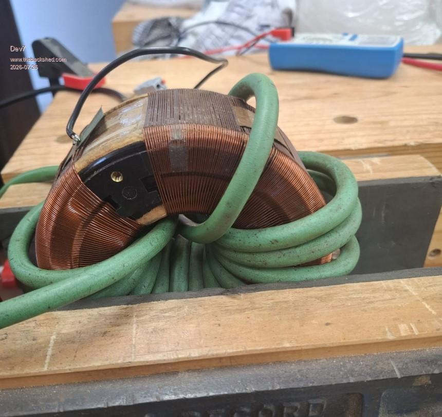
I ended up winding turns of 16mm^2 welding cable through the toroid against the inner circumference to see how many turns I could fit as a test. With a 60mm inner diameter I was only able to fit around 15 turns comfortably against the inner circumference (Welding cable is 9.2mm diameter). Are there any downsides to having a second layer of this thick cable in the inner window? I unfortunately don't see how I am going to fit 26-28 turns of this size cable in the toroid without squeezing it all in the middle.
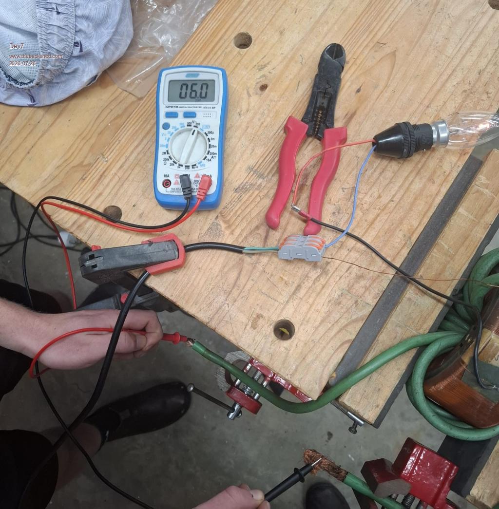
First test was done with a series 30W bulb and I measured 6V (13 turns) on the low voltage side. I was supplying the high voltage side with 235V mains.
235V/6V = 39.16 turns ratio 13 turns x 39.16 = 509 turns on the high voltage side
This tells me I will need around 26-28 turns to get 12-13V which was what I expected.
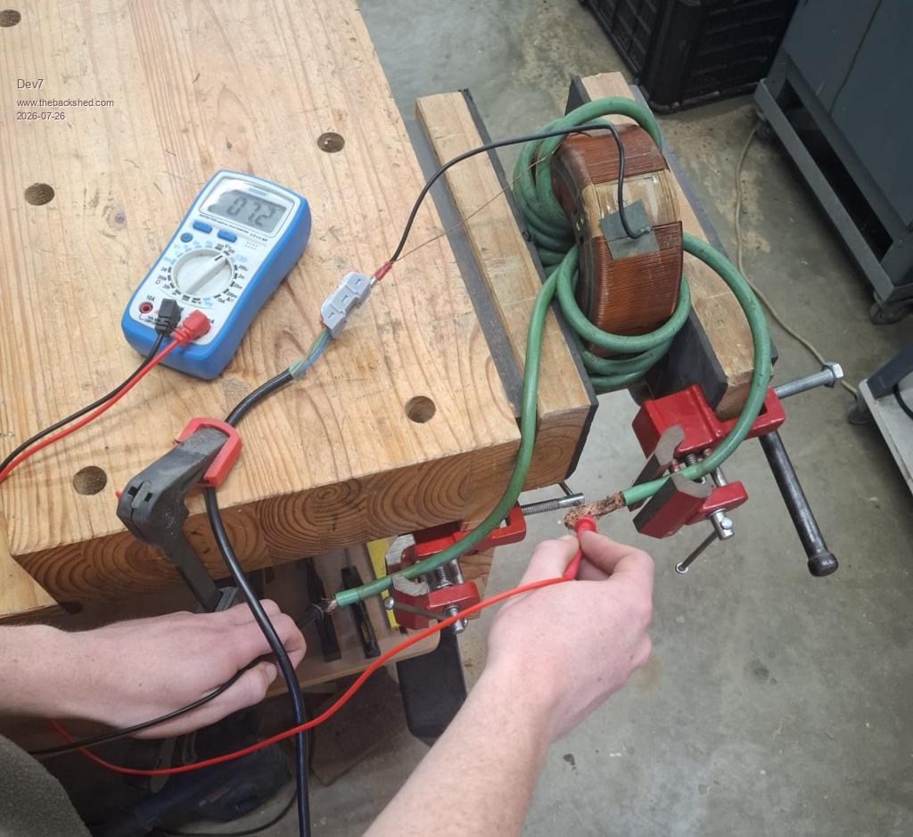
Second test was done with no series bulb and I measured 7.2V (13 turns) on the low voltage side. I'm assuming this is the no-load voltage whereas with the bulb test I measured a more realistic loaded voltage?
Let me know if you guys have any suggestions for fitting 26 turns of ~100A rated wire through this small window area. Maybe I will have to resort to using enameled copper wire in parallel.
Edited 2026-07-26 23:16 by Dev7
Godoh Guru Joined: 26/09/2020 Location: AustraliaPosts: 705
Posted: 09:40pm 26 Jul 2026
Copy link to clipboard
Print this post
Hi Dev there is no problem with filling the hole with the low voltage winding. As long as the turns go through the hole and around the outside then the transformer will work fine. Some battery cable is double insulated, it is fine to remove the outer layer of insulation as the voltage on the low voltage side is so low. I use mylar tape to insulate between the high and low voltage windings.
That welding cable looks very large for a 1kva inverter. Realistically you could use some 35mm cable for that job. Pete
disco4now Guru Joined: 18/12/2014 Location: AustraliaPosts: 1151
Posted: 11:03pm 26 Jul 2026
Copy link to clipboard
Print this post
My understanding is the light bulb is only to limit the inrush current at startup. You would then normally bypass it with a switch to taken your measurements. As you have no problems starting it without the light bulb you can take your measurements without it at all.
If taking the measurements with it in circuit you would need to measure the applied voltage at the start of the winding, so excluding any voltage drop across the bulb. So I think the 7.2V is the correct answer.F4H7FotSF4xGT

 Notice. New forum software under development. It's going to miss a few functions and look a bit ugly for a while, but I'm working on it full time now as the old forum was too unstable. Couple days, all good. If you notice any issues, please contact me.

 Print this post
.jpeg)
.jpeg)