
|

|
Forum Index : Solar : Load sharing PV arrays with the grid
| Page 1 of 2 |
|||||
| Author | Message | ||||
| LadyN Guru Joined: 26/01/2019 Location: United StatesPosts: 408 |
Thanks to all your input I have successfully set up two 1kW arrays and I measured them at 106V nominal each. That keeps the current at 9A which allows me to run inexpensive landscaping wire from the panels to the shed where I am working. Grid voltage seems to change between 112V - 116V over the day so (114 * (2 ** 0.5)) = 162V DC nominal. I wish I could parallel the arrays but I have repeatedly failed to do so using two diodes as their actual voltage varies a lot during the day from the 106V nominal. My plan was to get four more of these grid tie panels and add two each to each array, so array voltage is around 176V unloaded which gives me a 14V margin over the grid nominal. I am having a good time running almost everything I need off DC. All the wallwarts, power supplies work. I had to modify the toastmaker and oven to work off 220V but they work too. I need your help in: 1. TELLING me if this is all nonsense and I should go about it in a different way or if my calculations are wrong. 2. Figuring out how I can resolve loadsharing between the arrays. Right now I have to choose between either panel in isolation or both in series because putting them in parallel just does not work. Their voltage wanders enough that it reverse biases one of the two diodes almost all the time blocking one whole array from contributing power at any time 3. The bigger challenge will be getting the diode or to allow the arrays to loadshare with the grid. My panels go up in 35v increments (as measured practically under light loading. They are spec'd 40V OC and 33V Vmpp). With Grid DC being 162V DC nominal, I can get the array to output either 176V or 141V but neither is close enough to the grid's 162V (which itself changes over the day) It's entirely possible I'm overthinking this and putting three diodes in parallel to connect each power source to a common sink might work out well in practise because the load might cause whichever source that's active at that time to droop low enough when (over)loaded that the other source takes over until it can't provide all the power, and then the other source takes over and so on? If this post is too long and I should break it up, or I made calculation errors, please let me know |
||||
| Warpspeed Guru Joined: 09/08/2007 Location: AustraliaPosts: 4406 |
Go for 176v nominal, and don't worry about a slight difference in open circuit panel voltages. Common the different series panel arrays through high voltage diodes. The highest voltage panel will be pulled down in voltage slightly but both will load share just fine with each other, and the grid. Panels will deliver an increasing current at ANY voltage right down to zero volts. Paralleling up unequal open circuit voltages makes much less difference than many people think. The panels are current sources, and mismatched voltages only means that at extremely light loading one higher voltage string set of panels will take the entire load. But as you load it up much more, the others will start contributing as the voltage falls within their operating range. Sure that is going to be less efficient, but if you lose 5% or 10% its not really such a big deal. Just fit 15% more panels and laugh at the cynics. Running things direct from high voltage dc is sort of o/k for very light loads like wall packs, but you are going to have BIG problems with arcing at switches, so its a very bad thing with heavier loads and not advisable. Just be patient until you get your inverter going. You will need to be able to switch the solar panels on and off to isolate parts of the system for safe maintenance. Use proper dc rated two pole circuit breakers, and it best if you can do any switching under no load conditions. In other words switch off all your ac loads first (or on last) so the inverter runs unloaded. Then you can switch on or off the dc to the inverter which will only be idling. If you do it that way, the circuit breakers will last forever and give no trouble. If you weld the contacts, the circuit breaker becomes trash. Cheers, Tony. |
||||
| Keith Johnson Newbie Joined: 25/04/2019 Location: AustraliaPosts: 4 |
As was already said, the blocking diodes turn on if the individual panel groups voltage is higher than the voltage on the load side. Assuming this is charging a battery bank to allow for no daylight hours that voltage will be fairly constant. Measure the voltage across the diode it should be under 2 volts when turned on. Nominal silicon diode is 0.6 volts when conducting but some types can be lower than this. The current delivered from each bank of panels depends on the sun reaching it but it will all combine in the load. In the early days of solar 40 years ago everyone was using low voltage DC appliances. But the normal AC ones are much cheaper and these days dc to AC inverters are very cheap. I have 5 kW solar installed with a three phase inverter to match our 240 volt grid. Not thinking properly I knocked back an extra 1 kW of panels thinking the 5 kW inverter would not cope. Forgetting that solar panels never achieve the advertised power rating. With no care I would need at least 10 kW to run my house and shed as just the air conditioners would have a peak loading of about 10 kW. Being grid connect I let the power supplier make up the difference in the summer (46 C is not uncommon) I am somewhat confused as I thought the US grid was 110v 60 Hz ac so how are you connecting DC to this? Or have I missed something. Keith Longreach Queensland |
||||
| LadyN Guru Joined: 26/01/2019 Location: United StatesPosts: 408 |
Maybe you misunderstood me, or I'm doing the same or both but: 1. Flyback topology, like most household chargers off 80+V DC fed from a mix of PV DC and rectified grid work just fine in my experience. I actually think irregardless of topology, anything that works off rectified AC, like the computer PSU will work off 80+V DC fed from PV DC. THIS OF COURSE EXCLUDES boost convertors like PFC that higher end PSUs have, which unfortunately my computers have because back when I SPEC'D THEM I had not dreamed of going solar 2. Universal motors, like most household mixers, power tools, etc off 80+V DC fed from a mix of PV DC and rectified grid work just fine in my experience. This infact is currently causing me conflict with my family as they want to use solar DC ASAP instead of grid but don't appreciate the arcing issue caused by DC that does not have zero crossings and the switches in these tools and appliances are not gap rated (as needed for DC) but contact voltage rated (that works for AC) Grid power comes in, gets rectified to pulsing DC (more phases, less ripple so I'm thinking of going 2x 110v FROM THE GRID) and through a diode OR load shares with PV DC. This output is used above as in the two points keeping in mind how DC is different from AC (induction motors, PFC etc are a no go). Tony has written extensively about this before and I tried to capture it in two threads. |
||||
| azhaque Senior Member Joined: 21/02/2017 Location: PakistanPosts: 117 |
Natasha Salaams, You are going to get into a tiff with the utility company of your area for connecting diodes directly to the mains without isolation.  Attagirl azhaque |
||||
| LadyN Guru Joined: 26/01/2019 Location: United StatesPosts: 408 |
Salaam! Technically I would say the diode bridge provides isolation and of course, there is no risk of islanding/backfeed, which is the major concern the utility company has. My current concern with rectified Grid power is the HIGH RIPPLE content in the pulsing DC. I think, more phases, less ripple so I'm thinking of going 2x 110v FROM THE GRID. 3 phase would probably be even better. But yes, if the utility company looked at what I have, we could lose grid connection or even land up in court. I think time has come to change my real name and location from the profile! Thank you for the encouragement and the gentle reminder :) |
||||
| Warpspeed Guru Joined: 09/08/2007 Location: AustraliaPosts: 4406 |
Directly rectifying grid power so that dc flows back down the neutral wire is frowned upon by the electrical utilities for several reasons. In most countries we have a three phase supply with a grounded neutral. The pole transformer at the end of the street has a three phase transformer with the secondaries star connected. If we connect three diodes to that, to generate some dc directly with respect to neutral, it loads one half of the cycle only, and each of our star connected pole transformer windings will have dc superimposed on the ac. That will tend to staircase saturate each of the three secondary windings on each of the three separate limbs of the three phase transformer. But far worse than that, if we have three thirty amp phases, we can get (maybe) ninety amps of rectified dc. That all has to return down the neutral wire which may only be rated for thirty amps. So we might very easily burn out our neutral wire and start a fire. The neutral wire is NEVER protected by a fuse or a circuit breaker, so we may get into real trouble. Now the US electrical system is very different to the Aussie or European three phase system. The US pole transformer has only one single 220v winding with a centre tap that is grounded, producing two 110v phases and a grounded neutral. If we run two individual diodes from that to generate some dc with respect to neutral, it is not going to cause any problems at the pole transformer. The reason being both windings are on the same transformer limb. We might still get into trouble with overloading the neutral, but its much less of a risk with two phases rather than three. And if we are careful and understand what we are doing, its really not going to be an issue (technically). Another thing about this, we can use normal ac circuit breakers. Although half wave rectified dc current will be flowing, its interrupted completely each half cycle, and a continuous dc arc can not form. It may not be strictly legal in the US (I really do not know) there is absolutely minimal risk technically of something going wrong. On the other hand, in most other countries that have three phases, its far easier to get yourself into trouble, and I would not recommend doing it without going through a proper transformer. Cheers, Tony. |
||||
| LadyN Guru Joined: 26/01/2019 Location: United StatesPosts: 408 |
My current concerns with the grid dependent system are: 1. Ensuring islanding is handled. Correctly: my plan is to detect grid presence and if the presence fails, the grid rectifier is disconnected, including the feed to neutral 2. I need to think about how the utility company will react to: i. more current feeding to neutral than being sourced from live. KCL dictates net zero, so this clearly demonstrates that power is being generated outside the grid ii. HOW would this affect the electronic meter installed at our panel. A big no no is if it bills me for the current produced by my "offgrid" PV installation. iii. I will be growing the PV size in the future and gensets will be added as well in a few months, so this issue will need to be handled. WELL. How would grid tied GFCI react to this system? I have not thought about this scenario yet, but it's on my TODO. I am all ears. |
||||
| BenandAmber Guru Joined: 16/02/2019 Location: United StatesPosts: 961 |
Could you not possibly just go completely off-grid and say the heck with the power company If you can make buddies with someone at the recycling center you should be able to get some used batteries that would do you overnight till the sun comes back up again I have had very very good luck with a type of battery charger that is very dangerous to desulfate your batteries and after the batteries are completely played out you can get your money back out of them by recycling them again If you was just running lights computer charge your phone then your power usage at night could be very low if everybody agrees to do everything during the day be warned i am good parrot but Dumber than a box of rocks |
||||
| Boppa Guru Joined: 08/11/2016 Location: AustraliaPosts: 814 |
Probably the easiest way to get around several of your issues (dc on the lines, voltage matching needed, might be to invest in a variac for the AC line- if you get an isolated model, it would decouple the dc from the grid supply and give you the ability to vary the mains voltage to the diodes- giving you more precise matching if needed... 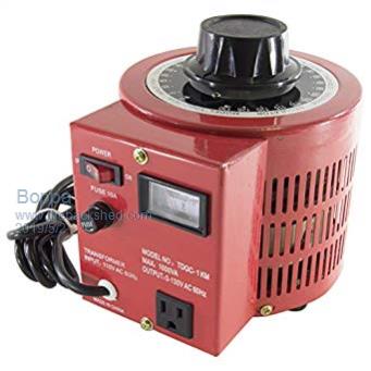 They are available in a variety of rating, from 100w up to thousands of watts... |
||||
| LadyN Guru Joined: 26/01/2019 Location: United StatesPosts: 408 |
Using a variac to provide isolation is a brilliant idea, thank you. I would be interested in each of your thoughts about how the utility company will react to: i. more current feeding to neutral than being sourced from live. KCL dictates net zero, so this clearly demonstrates that power is being generated outside the grid ii. HOW would this affect the electronic meter installed at our panel. A big no no is if it bills me for the current produced by my "offgrid" PV installation! I will be growing the PV size in the future and gensets will be added as well in a few months, so this issue will need to be handled. WELL. iii. How would grid tied GFCI react to this system? I have not thought about this scenario yet, but it's on my TODO. |
||||
| Boppa Guru Joined: 08/11/2016 Location: AustraliaPosts: 814 |
Using a fully isolated variac would again stop any feedback- although I can't see any way you would get 'more neutral current' anyway if my understanding of what you are doing is correct... 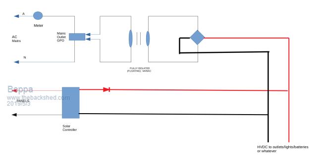 Even if you didn't use the variac (I would just to a: keep the power company happy and b: prevent any electrolysis issues from the DC with N/ grounding etc)- if I understand your circuit- it will neither backfeed the meter, nor send more current down the neutral than is being drawn from the active.. Adding a genpack is as easy as putting another bridge rectifier (the diamond on the grid feed circuit- AC top and bottom, + right red,- left black like on the grid feed- no need for the variac on this one though, as you don't care about DC on the supply, unlike the power company) and connecting it to the 'DC bus' lines (btw the drawing above is ignoring all the finer details like circuit breakers etc) If you aren't using a solar controller, then just the blocking diode is required... Adding more panel banks is as easy as copying the entire 'panel branch' from panels th HVDC bus on the right as many times as you wish One advantage of the gpo/outlet use with the variac is that it literally 'plug and play' on the grid side if you wish (sorry about the crudity of the drawing, I'm on my laptop and only have a basic drawing package on it) |
||||
| LadyN Guru Joined: 26/01/2019 Location: United StatesPosts: 408 |
That is the EXACT schematic (minus the transformer ofcourse)! So that I can loadshare with the grid, my PV GND and Grid neutral are electrically connected. The Grid is connected via a full bridge rectifier. I am hoping the diodes prevent backfeed into the grid. Now, what I don't understand is how the current sources from PV would flow when no current is being drawn from the rectified grid. My understanding is that current always follows the path of least resistance and PV is a higher impedance than the grid. Maybe what I should do is hook up some current sensors along the PV GND and Grid live, neutral paths and understand how electricity works. |
||||
| Boppa Guru Joined: 08/11/2016 Location: AustraliaPosts: 814 |
You shouldn't even need that PV (-) to grid N link (I assume that's what you meant by PV gnd??), if you are using a bridge rectifier on the grid supply, that's effectively cutting some of the diodes out of circuit... 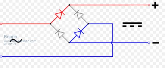 ] What you would be doing is joining the 'hump' instead of the wires passing but not joining- that effectively cuts that bottom 'blue' diode out of the circuit entirely.... (that blue (-) wire should be black, not blue) (I'm trying to imagine the waveform you would be getting both on the AC side and the DC side- my brain hurtz now...) OK figured it- you have effectively turned it into half wave rectifcation 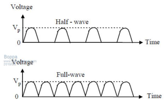 So you would be getting the top waveform, when you should be getting the bottom one (and effectively disconnected 3 of the 4 diodes in the bridge... |
||||
| LadyN Guru Joined: 26/01/2019 Location: United StatesPosts: 408 |
Ah, so when using half wave configuration, there is a chance of current generated by the PV array flowing into the Grid N, but when using a full wave configuration, the biasing of the diodes localize and isolate the PV array currents within the PV array? |
||||
| LadyN Guru Joined: 26/01/2019 Location: United StatesPosts: 408 |
The blue path still shows a way to Grid N from the PV array I think |
||||
| Boppa Guru Joined: 08/11/2016 Location: AustraliaPosts: 814 |
I don't want to be a damper on you or insult you in any way, but really- you should understand these things BEFORE playing with HVDC It is VERY intolerant of making mistakes... These levels of current and voltage could easily kill, or start a fire... That said, each of the voltage sources is its own independent circuit, if the PV is supplying all the voltage (and current) then the AC grid connect is effectively open circuited by its diodes- the panels (+) comes out the panel, through the 'bus' on the right of my drawing, through the loads and back to the panel (-)... the grid system there is completely non existent as far as the flow of electricity is concerned... Same when it's night, panels are now 0volts, no current flowing, all power passes from the bridge rectifier, through the bus, through the load and back to the bridge rectifier -, now the panels 'aren't there' IF you have load sharing happening then it gets interesting... If you panel voltages are higher than the grid rectifier output voltage, then the panels will produce up to their 100% rating depending on the load- if its only say 10W, the the panels, being the higher voltage will do all the work, all current comes from and goes to the panels- nothing- zero comes or goes to the grid wiring Lets bump the loads up, switch a few more lights on or whatever, we have hit the panels full output and gone sailing right past it... Lets go to double the panels output... Now this will drag the panels voltage down as they try to output more power than they are capable- this keeps dropping as the loads increase until we get to the stage that the panels voltage is equal to the grids rectifiers output voltage... half the power is coming from the panels, half from the grid rectifier... Even now- there is no excess current in the grid (-), or indeed the Neutral compared to the Active- the bridge rectifier is happily acting as a normal load to the grid, no nasties, no unbalanced currents anywhere- it's outputting it's current (say 5a) to the + bus- out to the loads, and back in the - bus, where exactly that same current will flow back into the - side of the grid rectifier Over at the panels, the same thing is happening, another 5A is coming out the +, joins in the + bus to give us our 10A required by the loads at this level, through the loads, back out the - bus and back to the panels... again the current in will be exactly the same as the current out on the solar leg... You will never get a situation where there is more current coming back in one side than went out the other... simply doesn't happen The circuit as I drew, which is 'almost' the same apart from that nasty neutral/negative link (get rid of it- not needed and could cause all sorts of noisy transients on your DC supply) will never backfeed the grid, affect the meter in any way apart from it registering the power used by you, wont make it read your solar generation and add to your bill |
||||
| LadyN Guru Joined: 26/01/2019 Location: United StatesPosts: 408 |
THANK YOU! I did not feel insulted with your response. I highly value you highlighting mi mistakes as that's the only way I learn. Thanks to each of you, I NOW know more than I did a month ago: I AM FAR from being competent but guided practise will get me there. THE ONLY way I can see progressing is share my thoughts here and being told where I am wrong, so I REALLY appreciate the insights you have shared because I don't know what I don't know. |
||||
| Boppa Guru Joined: 08/11/2016 Location: AustraliaPosts: 814 |
The blue shows the returning current- and HAS to be the same as the current that went out- thats just the way electricity works... Where the little 'hump' is where the two blues cross each other, that means they AREN'T joined, just 'jumping' over each other... (a joint is a solid dot when shown on a circuit diagram) What you have done atm is joined them- bad, gives a rapidly pulsing 'kinda' DC from the grid rectifier- you DON'T want this, you want a nice smooth dc supply, same as the panels (that's that nasty jumping up every now and then waveform I posted before- you don't want it, and that's what your current wiring setup is doing) |
||||
| Boppa Guru Joined: 08/11/2016 Location: AustraliaPosts: 814 |
This is the guts of the bridge rectifier- basically 4 diodes in a box... 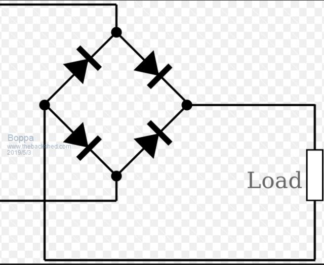 note that where the wires join, there is a solid dot (where each diode joins a wire or example), where they cross WITHOUT joining it will be that little 'hump' over the wire or just crossing with NO dot... compare to the blue wire diagram above and you will see that 'hump' where this one has no hump at that point, just crossing unconnected wires) Note that this one is turned 90 degrees to the right compared to the one above as well, sorry about that the 'red' is coming out the right and the 'blue' is on the left, top and bottom are the AC inputs What you have wired is this (see the extra connection???) 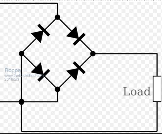 |
||||
| Page 1 of 2 |
|||||